2. 重庆交通大学 交通运输学院, 重庆 400074;
3. 同济大学 汽车学院, 上海 201804;
4. 东风小康汽车有限公司, 重庆 405321
2. College of Traffic & Transportation, Chongqing Jiaotong University, Chongqing 400074, P. R. China;
3. School of Automotive Studies, Tongji University, Shanghai 201804, P. R. China;
4. Dongfeng Xiaokang Automobile Co., Ltd., Chongqing 405321, P. R. China
永磁同步电机具有优良的动力输出性能和效率高等特点,在电动汽车领域得以广泛应用[1],而极槽配合对电机的齿槽转矩、振动噪声、输出转矩及其波动等有重要的影响[2]。相关文献资料大多给出的是指导性规则和常用的极槽配合[3],对高性能驱动电机,需要更加合理地选取极槽配合。
目前,国内外主要基于有限元法来研究不同极槽配合的电机性能。Liu等[4]建立了一种考虑槽开口和最大绕组系数的绕组函数,并借助有限元对比分析了不同极槽配合永磁电机的性能。Carraro等[5]讨论了永磁体性能和八种极槽配合对永磁电机转矩密度、齿槽转矩、转矩脉动和成本等的影响,并提出了一种基于有限元的优化设计程序。Wang等[6]利用有限元法分析了18槽10极电机绕组系数,并与传统的极槽配合对比分析了反电势、齿槽转矩、输出转矩和转矩脉动等性能。有限元法虽能计算复杂模型,但需重复建模,计算周期长;解析法可灵活调整解析模型任意结构参数,计算周期短,电磁参数等物理关系清晰,更加适合电机的初始设计[7],但同样对解析模型拓扑结构的完整性和精确性提出了更高的要求。Yin和Wu等[8-9]提出了一种子域与磁路混合模型,考虑了电机铁芯磁饱和,未定义定子齿尖。Zhu等[10]将电机划分为多个求解域并建立了矢量磁位方程,能够计算任意极槽数的永磁电机空载性能,但未考虑定子齿尖的影响。杨金歌等[11]在文献[10]的基础上,增加了定子齿尖,计算了齿槽转矩,张河山等[12]则进一步建立了考虑辅助槽的电机解析模型,研究了极弧系数、辅助槽尺寸和槽开口宽度对电机齿槽转矩和电磁转矩的影响。
文中则在文献[12]的基础上,建立了表贴式内转子永磁同步电机解析模型,进一步将永磁体和电枢磁场耦合,计算了电机空载和负载特性,通过有限元验证了解析模型的正确性。利用该解析模型,建立了尺寸约束边界,在保证电机硅钢片用量不变的情况下,分析研究了极槽配合对气隙磁密、齿槽转矩和输出转矩等性能的影响规律,60槽8极电机电气输出性能更佳,文中采用一种完全脱离有限元的解析方法对不同极槽配合电机性能进行分析,解析模型拓扑结构完整,计算精度高,为极槽配合的快速选取提供了新手段,大大缩短了电机设计周期。
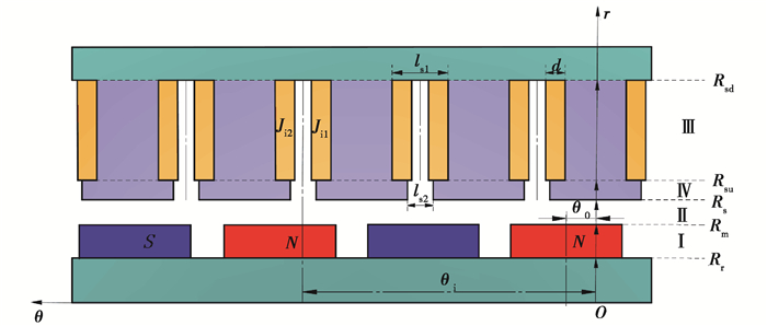
1 磁场解析建模 1.1 假设条件文中选用表贴式内转子永磁同步电机进行解析建模,图 1为该类电机的结构简图,其坐标系采用极坐标系。极坐标系r轴固定在定子齿中心位置,该结构示意图几何参数如下:
|
图 1 永磁同步电机结构简图 Fig. 1 Sche m atics of permanent-magnet synchronous motor |
1)Ⅰ、Ⅱ、Ⅲ、Ⅳ域分别为永磁体域、气隙域、电枢槽域和槽开口域;
2) θ0为零时刻转子N极中心位置处与r轴的夹角;
3) θi为第i个电枢槽、槽开口中心位置:θi=2π/Q(i-1/2);
4) ls1、ls2分别为电枢槽、槽开口弧度角。
为便于建模分析,作如下假设:
1) 永磁体材料的退磁曲线为线性;
2) 忽略绕组端部效应;
3) 定子槽内线圈边电流密度Ji1和Ji2均匀分布;
4) 定、转子铁芯材料的磁导率为无穷大;
5) 文中采用径向充磁的永磁体形式进行计算;
6) 永磁体域I的相对磁导率均相同且不为1。
在二维平面内,各子域磁场分布可由矢量磁位方程表示[13],为
| $ \frac{\partial^{2} \boldsymbol{A}_{i}}{\partial r}+\frac{1}{r} \frac{\partial \boldsymbol{A}_{i}}{\partial r}+\frac{1}{r^{2}} \frac{\partial^{2} \boldsymbol{A}_{i}}{\partial \theta^{2}}=-\mu_{0} J-\frac{\mu_{0}}{r}\left(\boldsymbol{M}_{\theta}-\frac{\partial \boldsymbol{M}_{r}}{\partial \theta}\right), $ | (1) |
式中:Ai代表各子域的矢量磁位;μ0为真空磁导率;Mr和Mθ分别为剩余磁化强度的径向和切向分量;J为电流密度。在Ⅰ、Ⅱ、Ⅳ域中,电流密度J=0;在Ⅱ、ⅲ、Ⅳ域中,不存在永磁体,所以Μr和Mθ皆为0。
1.2 永磁体域在永磁体域中,剩余磁化强度为
| $ \boldsymbol{M}=M_{r} \vec{r}+M_{\theta} \vec{\theta}, $ | (2) |
| $ {M_r} = \sum\limits_k {{M_R}} \cos \left[ {k\theta - k\left( {{\omega _r}t + {\theta _0}} \right)} \right] = \sum\limits_k {{M_{R{\rm{c}}}}} \cos k\theta + {M_{R{\rm{s}}}}\sin k\theta , $ | (3) |
| $ {M_\theta } = \sum\limits_k {{M_{{\theta ^\prime }}}} \sin \left[ {k\theta - k\left( {{\omega _r}t + {\theta _0}} \right)} \right] = \sum\limits_k {{M_{\theta {\rm{c}}}}} \cos k\theta + {M_{\theta {\rm{s}}}}\sin k\theta , $ | (4) |
式中:MRc=MRcos(kωrt+kθ0),MRs=MRsin(kωrt+kθ0),Mθc=-Mθ′sin(kωrt+kθ0),Mθs=Mθ′cos(kωrt+kθ0)。
当永磁体径向充磁时:
| $ M_{R}=\frac{4 p B r}{k {\rm{ \mathsf{ π} }} \mu_{0}} \sin \frac{k {\rm{ \mathsf{ π} }} a_{p}}{2 p}, $ | (5) |
| $ M_{\theta^{\prime}}=0, $ | (6) |
式中:k/p=1, 3, 5, ...,p为极对数;ap极弧系数。
由式(1)得永磁体域的泊松方程,为
| $ \left\{\begin{array}{l} \frac{\partial^{2} A_{\mathrm{I}}}{\partial r}+\frac{1}{r} \frac{\partial A_{\mathrm{I}}}{\partial r}+\frac{1}{r^{2}} \frac{\partial^{2} A_{\mathrm{I}}}{\partial \theta^{2}}=-\frac{\mu_{0}}{r}\left(M_{\theta}-\frac{\partial M_{r}}{\partial \theta}\right), \\ R_{\mathrm{r}}<r<R_{\mathrm{m}}, 0<\theta<2 {\rm{ \mathsf{ π} }}, \end{array}\right. $ | (7) |
由于铁芯磁导率无穷大,切向磁场强度满足条件:
| $ {\left. {{H_{1\theta }}} \right|_{r = {R_{\rm{r}}}}} = \frac{1}{{{\mu _0}{\mu _r}}}{\left. {{B_{1\theta }}} \right|_{r = {R_{\rm{r}}}}} - \frac{1}{{{\mu _r}}}{M_\theta } = 0, $ | (8) |
通过分离变量法得到永磁体子域通解:
| $ {A_{\rm{I}}} = \sum\limits_k {\left( {{Q_{1k}}{A_1} - {Q_{2k}}{M_{R{\rm{s}}}}} \right)} \cos (k\theta ) + \sum\limits_k {\left( {{Q_{1k}}{C_1} + {Q_{2k}}{M_{R{\rm{c}}}}} \right)} \sin (k\theta ), $ | (9) |
其中:A1和C1都为谐波系数。
| $ Q_{1 k}=\left(r / R_{\mathrm{m}}\right)^{k}+V_{1}\left(r / R_{\mathrm{r}}\right)^{-k}, $ |
| $ Q_{2 k}=\frac{\mu_{0}}{k^{2}-1}\left[R_{\mathrm{r}}\left(r / R_{\mathrm{r}}\right)^{-k}+k r\right], $ |
| $ V_{1}=\left(R_{\mathrm{r}} / R_{\mathrm{m}}\right)^{k} 。$ |
由式(1)可得气隙域的拉普拉斯方程为
| $ \left\{\begin{array}{l} \frac{\partial^{2} A_{\mathrm{II}}}{\partial r}+\frac{1}{r} \frac{\partial A_{\mathrm{II}}}{\partial r}+\frac{1}{r^{2}} \frac{\partial^{2} A_{\mathrm{II}}}{\partial \theta^{2}}=0, \\ R_{\mathrm{m}}<r<R_{\mathrm{s}}, 0<\theta<2 {\rm{ \mathsf{ π} }}。\end{array}\right. $ | (10) |
通过分离变量法得到气隙域通解,为
| $ A_{\mathrm{II}}=\sum\limits_{k}\left[A_{2}\left(r / R_{\mathrm{s}}\right)^{k}+B_{2}\left(r / R_{\mathrm{m}}\right)^{-k}\right] \cos (k \theta)+\sum\limits_{k}\left[C_{2}\left(r / R_{\mathrm{s}}\right)^{k}+D_{2}\left(r / R_{\mathrm{m}}\right)^{-k}\right] \sin (k \theta), $ | (11) |
式中,A2和C2都为谐波系数。
1.4 电枢槽域由式(1)得到电枢槽域的泊松方程,为
| $ \left\{\begin{array}{l} \frac{\partial^{2} A_{\mathrm{III}}}{\partial r}+\frac{1}{r} \frac{\partial A_{\mathrm{III}}}{\partial r}+\frac{1}{r^{2}} \frac{\partial^{2} A_{\mathrm{III}}}{\partial \theta^{2}}=-\mu_{0} J, \\ R_{\mathrm{su}}<r<R_{\mathrm{sd}}, \theta_{i}-l_{\mathrm{s} 1} / 2<\theta<\theta_{i}+l_{\mathrm{s} 1} / 2。\end{array}\right. $ | (12) |
满足方程的边界条件为
| $ \left\{ {\begin{array}{*{20}{l}} {{{\left. {\frac{{\partial {A_{{\rm{III }}}}}}{{\partial \theta }}} \right|}_{\theta = {\theta _i} - \frac{{{l_{{\rm{s1}}}}}}{2}}} = 0,}\\ {{{\left. {\frac{{\partial {A_{{\rm{III }}}}}}{{\partial \theta }}} \right|}_{\theta = {\theta _i} + \frac{{{l_{{\rm{s1}}}}}}{2}}} = 0,}\\ {{{\left. {\frac{{\partial {A_{{\rm{III }}}}}}{{\partial r}}} \right|}_{r = {R_{{\rm{sd }}}}}} = 0}。\end{array}} \right. $ |
在电枢槽域,绕组形式采用图 1所示的非重叠绕组,对于非重叠绕组,电流密度的分布形式为
| $ J = \left\{ {\begin{array}{*{20}{cl}} {{J_{i1}},}&{{\theta _i} - \frac{{{l_{s1}}}}{2} < \theta < {\theta _i} - \frac{{{l_{{\rm{s1}}}}}}{2} + d,}\\ {0,}&{{\theta _i} - \frac{{{l_{{\rm{s1}}}}}}{2} + d < \theta < {\theta _i} + \frac{{{l_{{\rm{s1}}}}}}{2} - d,}\\ {{J_{i2}},}&{{\theta _i} + \frac{{{l_{{\rm{s1}}}}}}{2} - d < \theta < {\theta _i} + \frac{{{l_{{\rm{s1}}}}}}{2} + d,}\\ {0,}&{{\theta _i} + \frac{{{l_{{\rm{s1}}}}}}{2} + d < \theta < {\theta _i} + \frac{{3{l_{{\rm{s1}}}}}}{2} - d,}\\ {{J_{i1}},}&{{\theta _i} + \frac{{3{l_{{\rm{s1}}}}}}{2} - d < \theta < {\theta _i} + \frac{{3{l_{{\rm{s1}}}}}}{2}}。\end{array}} \right. $ | (13) |
将式(13)展开成傅里叶级数,可得电流密度为
| $ J=J_{i 0}+\sum\limits_{n} J_{i n} \cos \left[E_{n}\left(\theta+l_{\mathrm{s} 1} / 2-\theta_{i}\right)\right], $ | (14) |
式中:
| $ J_{i 0}=\left(J_{i 1}+J_{i 2}\right) d / l_{\mathrm{s} 1}, $ |
| $ J_{i n}=\frac{2}{n {\rm{ \mathsf{ π} }}}\left(J_{i 1}+J_{i 2} \cos n {\rm{ \mathsf{ π} }}\right) \sin \left(n {\rm{ \mathsf{ π} }} d / l_{\mathrm{s} 1}\right), $ |
| $ E_{n}=n {\rm{ \mathsf{ π} }} / l_{\mathrm{s} 1}。$ |
联立式(12)和式(14),利用分离变量法可得电枢槽域通解,为
| $ A_{\mathrm{III}}=A_{0}+\sum\limits_{n} A_{n} \cos \left[E_{n}\left(\theta+l_{\mathrm{s} 1} / 2-\theta_{i}\right)\right], $ | (15) |
式中:B3为谐波系数;
由式(1)可得槽开口域的拉普拉斯方程:
| $ \left\{\begin{array}{l} \frac{\partial^{2} A_{\mathrm{IV}}}{\partial r}+\frac{1}{r} \frac{\partial A_{\mathrm{IV}}}{\partial r}+\frac{1}{r^{2}} \frac{\partial^{2} A_{\mathrm{IV}}}{\partial \theta^{2}}=0, \\ R_{\mathrm{s}}<r<R_{\mathrm{su}}, \\ \theta_{i}-l_{\mathrm{s} 2} / 2<\theta<\theta_{i}+l_{\mathrm{s} 2} / 2。\end{array}\right. $ | (16) |
满足方程的边界条件为
| $ \left\{\begin{array}{l} \left.\frac{\partial A_{\mathrm{IV}}}{\partial \theta}\right|_{\theta=\theta_{i}-\frac{l_{\mathrm{s} 2}}{2}}=0 ,\\ \left.\frac{\partial A_{\mathrm{IV}}}{\partial \theta}\right|_{\theta=\theta_{i}+\frac{l_{\mathrm{s} 2}}{2}}=0。\end{array}\right. $ |
利用分离变量法可得槽开口域通解:
| $ A_{\mathrm{IV}}=A_{40}+B_{40} \ln r+\sum\limits_{m}\left[A_{4}\left(r / R_{\mathrm{su}}\right)^{F_{m}}+B_{4}\left(r / R_{\mathrm{s}}\right)^{-F_{m}}\right] \cdot \cos \left[F_{m}\left(\theta+l_{\mathrm{s} 2} / 2-\theta_{i}\right)\right], $ | (17) |
式中:A4和B4为谐波系数;Fm=mπ/ls2。
2 边界条件与谐波系数求解电机解析模型被分成4个子域,则需要通过磁场的边界条件把各子域连接起来。由磁密B和磁场强度H性质可知,磁密B的法向分量和磁场强度H的切向分量在各子域的交界面具有连续性[14],则可通过该边界条件求解出各子域矢量磁位通解的谐波系数。
2.1 永磁体域和气隙域分界面永磁体域和气隙域分界面边界条件,为
| $ \left.A_{\mathrm{I}}\right|_{r=R_{\mathrm{m}}}=\left.A_{\mathrm{II}}\right|_{r=R_{\mathrm{m}}}, \quad 0 \leqslant \theta \leqslant 2 {\rm{ \mathsf{ π} }}, $ | (18) |
| $ \left.H_{\mathrm{I} \theta}\right|_{r=R_{\mathrm{m}}}=\left.H_{\mathrm{II} \theta}\right|_{r=R_{\mathrm{m}}}, \quad 0 \leqslant \theta \leqslant 2 {\rm{ \mathsf{ π} }}, $ | (19) |
由式(18)和式(19)可得:
| $ A_{2} V_{2}+B_{2}=\frac{1}{{\rm{ \mathsf{ π} }}} \int\limits_{0}^{2 {\rm{ \mathsf{ π} }}} A_{\mathrm{I}} \cos (k \theta) \mathrm{d} \theta , $ | (20) |
| $ C_{2} V_{2}+D_{2}=\frac{1}{{\rm{ \mathsf{ π} }}} \int\limits_{0}^{2 {\rm{ \mathsf{ π} }}} A_{\mathrm{I}} \sin (k \theta) \mathrm{d} \theta , $ | (21) |
| $ \left.\frac{1}{\mu_{0} \mu_{r}} \frac{\partial A_{\mathrm{I}}}{\partial r}\right|_{r=R_{\mathrm{m}}}=\left.\frac{1}{\mu_{0}} \frac{\partial A_{\mathrm{II}}}{\partial r}\right|_{r=R_{\mathrm{m}}}, $ | (22) |
式中,V2=(Rm/Rs)k。
2.2 电枢槽域和槽开口域分界面电枢槽域和槽开口域分界面边界条件如下:
| $ \left.A_{\mathrm{III}}\right|_{r=R_{\mathrm{su}}}=\left.A_{\mathrm{IV}}\right|_{r=R_{\mathrm{su}}}, \theta_{i}-\frac{l_{\mathrm{s} 2}}{2} \leqslant \theta \leqslant \theta_{i}+\frac{l_{\mathrm{s} 2}}{2}, $ | (23) |
| $ \left\{\begin{array}{lc} \left.H_{\mathrm{III} \theta}\right|_{r=R_{\mathrm{su}}}=\left.H_{\mathrm{IV} \theta}\right|_{r=R_{\mathrm{su}}}, &\theta_{i}-\frac{l_{\mathrm{s} 2}}{2} \leqslant \theta \leqslant \theta_{i}+\frac{l_{\mathrm{s} 2}}{2}, \\ \left.H_{\mathrm{III} \theta}\right|_{r=R_{\mathrm{su}}}=0, & \text { 其他 }_{\circ} \end{array}\right. $ | (24) |
将式(23)和式(24)展开成傅里叶级数可得:
| $ \begin{gathered} A_{4}+B_{4} V_{4}=\frac{2}{l_{{s} 2}} \int\limits_{\theta_{i}-l_{\mathrm{s} 2} / 2}^{\theta_{i}+l_{\mathrm{s} 2}/ 2} \sum\limits_{n} B_{3}\left(V_{3}^{2}+1\right)+\mu_{0} \frac{J_{i n}}{E_{n}\left(E_{n}^{2}-4\right)}\left(R_{\mathrm{su}}^{2}-2 R_{\mathrm{sd}}^{2} V_{3}\right) \cdot \\ \cos \left[E_{n}\left(\theta+l_{\mathrm{s} 1} / 2-\theta_{i}\right)\right] \cdot \cos \left[F_{m} \cdot\left(\theta+l_{\mathrm{s} 2} / 2-\theta_{i}\right)\right], \end{gathered} $ | (25) |
| $ B_{\mathrm{IV} \theta}=B_{0}+\sum\limits_{m} B_{n} \cos \left[E_{n}\left(\theta+l_{\mathrm{s} 1} / 2-\theta_{i}\right)\right], $ | (26) |
| $ \begin{gathered} \sum\limits_{n}\left[-\frac{1}{R_{\mathrm{su}}} E_{n} B_{3}\left(V_{3}^{2}-1\right)-\frac{2 \mu_{0}}{R_{\mathrm{su}}} \cdot \frac{J_{\mathrm{in}}}{E_{n}^{2}-4} \cdot\left(R_{\mathrm{su}}^{2}-R_{\mathrm{sd}}^{2} V_{3}\right)\right]= \\ \frac{2}{l_{\mathrm{s1}}} \int\limits_{\theta_{i}-l_{\mathrm{s 2}} / 2}^{\theta_{i}+l_{\mathrm{s} 2} / 2}-\frac{B_{40}}{R_{\mathrm{su}}} \cos \left[E_{n}\left(\theta+l_{\mathrm{s} 1} / 2-\theta_{i}\right)\right] \mathrm{d} \theta+\frac{2}{l_{\mathrm{s} 1}} \int\limits_{\theta_{i}-l_{\mathrm{s 2}} / 2}^{\theta_{i}+l_{\mathrm{s 2}} / 2} \sum\limits_{m}\left[-\frac{1}{R_{\mathrm{su}}} F_{m}\left(A_{4}-B_{4} V_{4}\right)\right] \\ \cos \left[F_{m}\left(\theta+l_{\mathrm{s} 2} / 2-\theta_{i}\right) \cos \left[E_{n}\left(\theta+l_{\mathrm{s} 1} / 2-\theta_{i}\right)\right] \mathrm{d} \theta\right.。\end{gathered} $ | (27) |
式中:求解系数B40=μ0Ji0(ls1/ls2·(Rsd2-Rsu2)/2);V4=(Rs/Rsu)Fm。
2.3 气隙域和槽开口域分界面气隙域和槽开口域分界面边界条件为
| $ \left.A_{\mathrm{II}}\right|_{r=R_{\mathrm{s}}}=\left.A_{\mathrm{IV}}\right|_{r=R_{\mathrm{s}}}, \quad \theta_{i}-\frac{l_{\mathrm{s} 2}}{2} \leqslant \theta \leqslant \theta_{i}+\frac{l_{\mathrm{s} 2}}{2}, $ | (28) |
| $ \left\{\begin{array}{lc} \left.H_{\mathrm{II} \theta}\right|_{r=R_{\mathrm{s}}}=\left.H_{\mathrm{IV} \theta}\right|_{r=R_{\mathrm{s}}}, & \theta_{i}-\frac{l_{\mathrm{s} 2}}{2} \leqslant \theta \leqslant \theta_{i}+\frac{l_{\mathrm{s} 2}}{2}, \\ \left.H_{\mathrm{II} \theta}\right|_{r=R_{\mathrm{s}}}=0, & \text { 其他。} \end{array}\right. $ | (29) |
将式(28)和式(29)展开成傅里叶级数可得:
| $ \begin{gathered} \left.A_{\mathrm{IV}}\right|_{r=R_{\mathrm{s}}}=\frac{1}{l_{s 2}} \int\limits_{\theta_{i}-l_{\mathrm{s2}} / 2}^{\theta_{i}+l_{\mathrm{s2}} / 2} \left.A_{\mathrm{II}}\right|_{r=R_{s}} \mathrm{~d} \theta+ \\ \sum\limits_{\mathrm{m}}\left\{\frac{1}{l_{\mathrm{s} 2}} \int\limits_{\theta_{i}-l_{\mathrm{s2}} / 2}^{\theta_{i}+l_{\mathrm{s2}} / 2} \left.A_{\mathrm{II}}\right|_{r=R_{\mathrm{s}}} \cos \left[F_{m}\left(\theta+\frac{l_{\mathrm{s} 2}}{2}-\theta_{i}\right)\right] \mathrm{d} \theta \cdot \cos \left[F_{m}\left(\theta+\frac{l_{\mathrm{s} 2}}{2}-\theta_{i}\right)\right]\right\}, \end{gathered} $ | (30) |
| $ \begin{gathered} -\left.\frac{\partial A_{\mathrm{II}}}{\partial \mathrm{r}}\right|_{r=R_{\mathrm{s}}}=\sum\limits_{k}\left\{\frac{1}{{\rm{ \mathsf{ π} }}} \sum\limits_{i} \int\limits_{\theta_{i}-l_{\mathrm{s} 2} / 2}^{\theta_{i}+l_{\mathrm{s} 2} / 2}-\left.\frac{\partial A_{\mathrm{IV}}}{\partial r}\right|_{r=R_{\mathrm{s}}} \cos (k \theta) \mathrm{d} \theta \cdot \cos (k \theta)+\right. \\ \left.\frac{1}{{\rm{ \mathsf{ π} }}} \sum\limits_{i} \int\limits_{\theta_{i}-l_{\mathrm{s2}} / 2}^{\theta_{i}+l_{\mathrm{s2}} / 2}-\left.\frac{\partial A_{\mathrm{IV}}}{\partial r}\right|_{r=R_{s}} \sin (k \theta) \mathrm{d} \theta \cdot \sin (k \theta)\right\}。\end{gathered} $ | (31) |
根据矢量磁位和磁密关系,得到其径向分量和切向分量:
| $ B_{\mathrm{IIr}}=\frac{1}{r} \frac{\partial A_{\mathrm{II}}}{\partial \theta}=\sum\limits_{k} B_{r \mathrm{s}} \sin (k \theta)+\sum\limits_{k} B_{r \mathrm{c}} \cos (k \theta), $ | (32) |
| $ B_{\mathrm{II}\theta}=-\frac{\partial A_{\mathrm{II}}}{\partial r}=\sum\limits_{k} B_{\theta \mathrm{c}} \cos (k \theta)+\sum\limits_{k} B_{\theta \mathrm{s}} \sin (k \theta), $ | (33) |
式中:Brs=-k[A2(r/Rs)k+B2(r/Rm)-k]/r,Brc=k[C2(r/Rs)k+D2(r/Rm)-k]/r,Bθc=-k[A2(r/Rs)k-B2(r/Rm)-k]/r,Bθs=-k[C2(r/Rs)k-D2(r/Rm)-k]/r。
3.2 磁链由矢量磁位的分布和文中假设条件,可求得左侧和右侧线圈边的磁链分布:
| $ {\psi _{i1}} = {l_{\rm{a}}}{N_{\rm{c}}}/{A_{\rm{c}}}\int\limits_{{R_{{\rm{sd}}}}}^{{R_{{\rm{su}}}}} {\int\limits_{{\theta _i} - {l_{{\rm{s}}1}}/2}^{{\theta _i} - {l_{{\rm{s}}1}}/2 + d} {{A_{{\rm{III}}}}} } r{\rm{d}}r{\rm{d}}\theta = {l_{\rm{a}}}{N_{\rm{c}}}/{A_{\rm{c}}}\left[ {{Z_{i0}}d + \sum\limits_n {\left( {{Z_{in}}/{E_n}} \right)} \sin \left( {{E_n}d} \right)} \right], $ | (34) |
| $ {\psi _{i2}} = {l_{\rm{a}}}{N_{\rm{c}}}/{A_{\rm{c}}}\int\limits_{{R_{{\rm{su}}}}}^{{R_{{\rm{sd}}}}} {\int\limits_{{\theta _i} - {l_{{\rm{s}}1}}/2 - d}^{{\theta _i} - {l_{{\rm{s}}1}}/2} {{A_{{\rm{III}}}}} } r{\rm{d}}r{\rm{d}}\theta = {l_{\rm{a}}}{N_{\rm{c}}}/{A_{\rm{c}}}\left[ {{Z_{i0}}d + \sum\limits_n {\left( {{Z_{in}}/{E_n}} \right)} \sin \left( {n{\rm{ \mathsf{ π} }} - {E_n}d} \right)} \right], $ | (35) |
式中:
由式(34)和式(35)可得三相总磁链为:
| $ \left[\begin{array}{l} \varphi_{\mathrm{A}} \\ \varphi_{\mathrm{B}} \\ \varphi_{\mathrm{C}} \end{array}\right]=\boldsymbol{C}\left[\begin{array}{lllll} \psi_{1,1} & \psi_{1,2} & \ldots & \psi_{48,1} & \psi_{48,2} \end{array}\right]^{\mathrm{T}}, $ | (36) |
式中,C为绕组分布矩阵。
3.3 反电势由磁链对时间的微分可得各相反电势,其中A相反电势为
| $ e_{\mathrm{A}}=-\mathrm{d} \varphi_{\mathrm{A}} / \mathrm{d} t。$ | (37) |
取气隙域的中心位置ra=(Rm+Rs)/2,利用麦克斯韦张量法求得:
| $ \begin{gathered} T=\left.\left.\frac{l_{\mathrm{a}} r_{\mathrm{a}}^{2}}{\mu_{0}} \int\limits_{0}^{2 {\rm{ \mathsf{ π} }}} B_{\mathrm{IIr}} \right|_{r=r_{\mathrm{a}}} \cdot B_{\mathrm{II} \theta}\right|_{r=r_{\mathrm{a}}} \mathrm{d} \theta= \\ \left(\frac{{\rm{ \mathsf{ π} }} l_{\mathrm{a}} r_{\mathrm{a}}^{2}}{\mu_{0}}\right) \sum\limits_{k}\left[\left.\left.B_{r \mathrm{c}}\right|_{r=r_{\mathrm{a}}} \cdot B_{\theta \mathrm{c}}\right|_{r=r_{\mathrm{a}}}+\left.\left.B_{r \mathrm{s}}\right|_{r=r_{\mathrm{a}}} \cdot B_{\theta \mathrm{s}}\right|_{r=r_{\mathrm{a}}}\right], \end{gathered} $ | (38) |
式中:空载时,T为齿槽转矩;负载时,T为输出转矩。
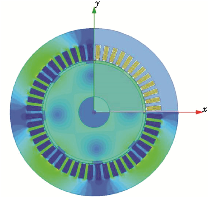
4 有限元验证 4.1 样机参数文中选用常用的48槽8极电动汽车用永磁同步电机作为研究对象,有限元模型如图 2,其主要参数如表 1所示,其绕组分布形式为
| $ \boldsymbol{C}_{48}=\left[\begin{array}{llll} \boldsymbol{C}_{1} & \boldsymbol{C}_{1} & \boldsymbol{C}_{1} & \boldsymbol{C}_{1} \end{array}\right], $ | (39) |
| $ \begin{array}{l} \boldsymbol{C}_{1} =\left[\begin{array}{cccccccccccc} 1 & 1 & 1 & 0 & 0 & 0 & 0 & 0 & 0 & 0 & 0 & -1 \\ 0 & 0 & 0 & 0 & 0 & 0 & 0 & 1 & 1 & 1 & 1 & 0 \\ 0 & 0 & 0 & -1 & -1 & -1 & -1 & 0 & 0 & 0 & 0 & 0 \end{array}\right. \\ \left.\begin{array}{cccccccccccc}-1 & -1 & -1 & 0 & 0 & 0 & 0 & 0 & 0 & 0 & 0 & 1 \\ 0 & 0 & 0 & 0 & 0 & 0 & 0 & -1 & -1 & -1 & -1 & 0 \\ 0 & 0 & 0 & 1 & 1 & 1 & 1 & 0 & 0 & 0 & 0 & 0 \end{array}\right] 。\end{array} $ |
|
图 2 电机有限元模型 Fig. 2 FEM model |
| 表 1 电机主要参数 Table 1 Main parameters of motor |
该矩阵的行分别表示绕组的A、B、C三相,列对应图 1所示绕组分布,从原点向θ方向依次排列。
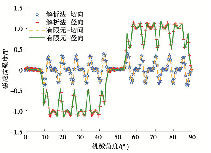
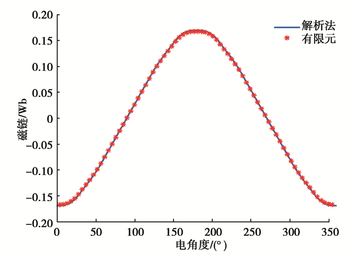
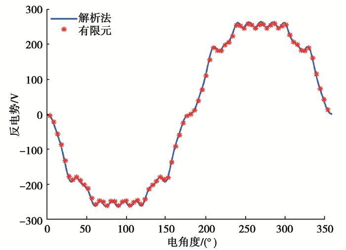
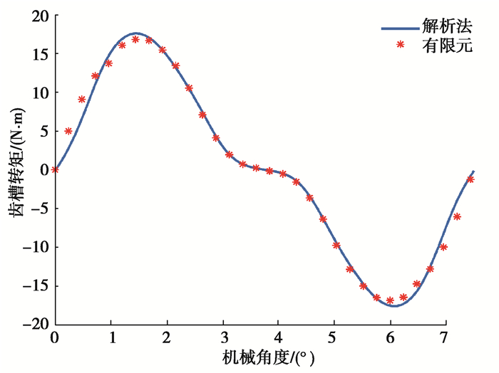
4.2 空载特性验证在电机额定转速为4 000 r/min的空载工况下,提取有限元模型气隙中心位置r=(Rm+Rs)/2处的径向和切向气隙磁密,并与解析法进行对比,结果如图 3所示,解析模型的径向和切向分量与有限元结果高度拟合。图 4、图 5和图 6分别为该工况下的A相空载磁链、A相空载反电势和齿槽转矩,可以看出:解析解和有限元结果拟合度很好,进一步验证了该解析方法的正确性。
|
图 3 空载气隙磁密 Fig. 3 No-load air-gap flux density |
|
图 4 A相空载磁链 Fig. 4 No-load flux curve of A phase |
|
图 5 A相反电势 Fig. 5 Back EMF of A phase |
|
图 6 齿槽转矩 Fig. 6 Cogging torque |
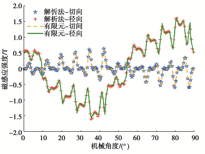
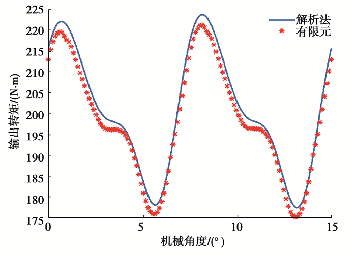
在额定电流为200 A的负载工况下,依旧选取气隙中心r=(Rm+Rs)/2,得到图 7所示负载气隙磁密分布图,解析解与有限元模型拟合度很好,只是在尖峰位置处有微小差异。图 8为电机输出转矩,从图中可看出:解析解与有限元结果拟合性较好,最大误差为1.2%,且分布趋势一致,进一步证明了该解析方法的正确性。
|
图 7 负载气隙磁密 Fig. 7 On-load air-gap flux density |
|
图 8 输出转矩 Fig. 8 Output torque |
极槽配合是电机最基本的设计参数,对电机的功率密度、效率和振动噪声等性能有很大影响,所以在电机的初步设计中,极槽配合的选取显得格外重要。在选取极槽配合时,需要考虑气隙磁密、齿槽转矩、输出转矩等性能。
依据每极每相槽数,极槽配合可以分为整数槽和分数槽[15]两类,车用高速内转子电机一般为多槽少极的配合形式,转子极数主要为4、6、8三种,文献[4-5]提出多极电机有更好的转矩输出性能,本文采用转子极数为8级,定子槽数为36槽、60槽的分数槽和48槽的整数槽电机进行研究,且36槽和60槽的绕组分布矩阵分别如式(40)和式(41)所示。利用文中所建立的解析模型,计算分析空载气隙磁密、齿槽转矩特性、负载气隙磁密和输出转矩特性。
| $ \boldsymbol{C}_{36}=\left[\begin{array}{lll} \boldsymbol{C}_{2} & \boldsymbol{C}_{2} & \boldsymbol{C}_{2} & \boldsymbol{C}_{2} \end{array}\right], $ | (40) |
| $ \boldsymbol{C}_{60}=\left[\begin{array}{lll} \boldsymbol{C}_{3} & \boldsymbol{C}_{3} & \boldsymbol{C}_{3} & \boldsymbol{C}_{3} \end{array}\right], $ | (41) |
其中:
| $ \boldsymbol{C}_{2}=\left[\begin{array}{cccccccccccccccccc} 0 & 1 & 1 & 1 & 0 & 0 & 0 & 0 & 0 & 0 & -1 & -1 & -1 & 0 & 0 & 0 & 0 & 0 \\ -1 & 0 & 0 & 0 & 0 & 0 & 0 & 1 & 1 & 1 & 0 & 0 & 0 & 0 & 0 & 0 & -1 & -1 \\ 0 & 0 & 0 & 0 & -1 & -1 & -1 & 0 & 0 & 0 & 0 & 0 & 0 & 1 & 1 & 1 & 0 & 0 \end{array}\right], $ |
| $ \begin{array}{l} \boldsymbol{C}_{3}=\left[\begin{array}{ccccccccccccccc} 0 & 1 & 0 & 1 & 0 & 1 & 0 & 0 & 0 & 0 & -1 & 0 & -1 & 0 & -1 \\ 0 & 0 & 0 & 0 & 0 & 0 & 1 & 0 & 1 & 0 & 0 & 1 & 0 & 1 & 0 \\ - & 1 & 0 & -1 & 0 & -1 & 0 & 0 & -1 & 0 & -1 & 0 & 0 & 0 & 0 \end{array}\right.\\ \ \ \ \ \ \ \left.\begin{array}{ccccccccccccccc} 0 & 0 & -1 & 0 & -1 & 0 & 0 & 0 & 0 & 0 & 0 & 1 & 0 & 1 & 0 & & \\ 1 & 0 & 0 & 0 & 0 & -1 & 0 & -1 & 0 & -1 & 0 & 0 & -1 & 0 & -1 & & \\ 0 & 1 & 0 & 1 & 0 & 0 & 1 & 0 & 1 & 0 & 1 & 0 & 0 & 0 & 0 & & \end{array}\right]。\end{array} $ |
文中以电机基本拓扑结构尺寸和铁芯用量不变为前提来对比不同极槽配合下电机的性能。在控制电机轴向长度、永磁体厚度、定转子直径、定子轭高、齿尖厚度和定子槽开口大小等尺寸不变的情况下,通过改变定子槽宽角ls1的大小来保证电机定子槽总面积不变,从而使定子铁芯用量保持不变。定子槽总面积如式(42)所示,其中Z为定子槽数。
| $ A(Z)=\left(R_{\mathrm{sd}}+R_{\mathrm{su}}\right) \cdot {\rm{ \mathsf{ π} }} l_{\mathrm{s} 1} h Z / 360 , $ | (42) |
| $ A(36)=A(48)=A(60), $ | (43) |
在误差允许范围,为了计算方便,h约等于定子轭高,则这3种极槽配合电机所得定子槽宽角如表 2所得,其他相关参数则依旧采用表 1所示参数。
| 表 2 电机变动参数 Table 2 Variable parameters of motor |
对以上3种极槽配合形式的电机进行了解析计算,得到齿槽转矩、气隙磁密和其主要谐波分布。由图 3和图 9可知,径向气隙磁密峰值远大于切向气隙磁密,极槽配合对空载径向和切向气隙磁密的幅值影响不大,但对其分布有较大影响,这是由于定子开槽引起的,随着槽数的增多,气隙磁密波形尖峰分布更密。从图 10看出,径向气隙磁密前9阶谐波幅值相差很小,随着阶次的升高,60槽8极电机的谐波含量明显减小。齿槽转矩分布如图 11所示,随着槽数的增加,齿槽转矩波动频率增加,60槽8极齿槽转矩峰值远小于其他2种极槽配合,分别降低了96.38%和98.23%,如表 3所示。
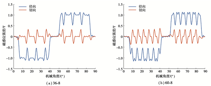
|
图 9 空载气隙磁密 Fig. 9 No-load air-gap flux density |
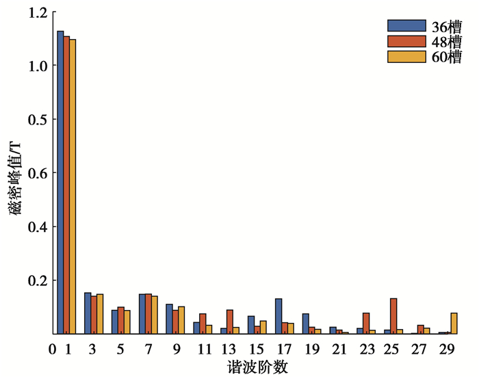
|
图 10 空载径向气隙磁密谐波分布 Fig. 10 Harmonic spectrum of no-load radial air gap flux |
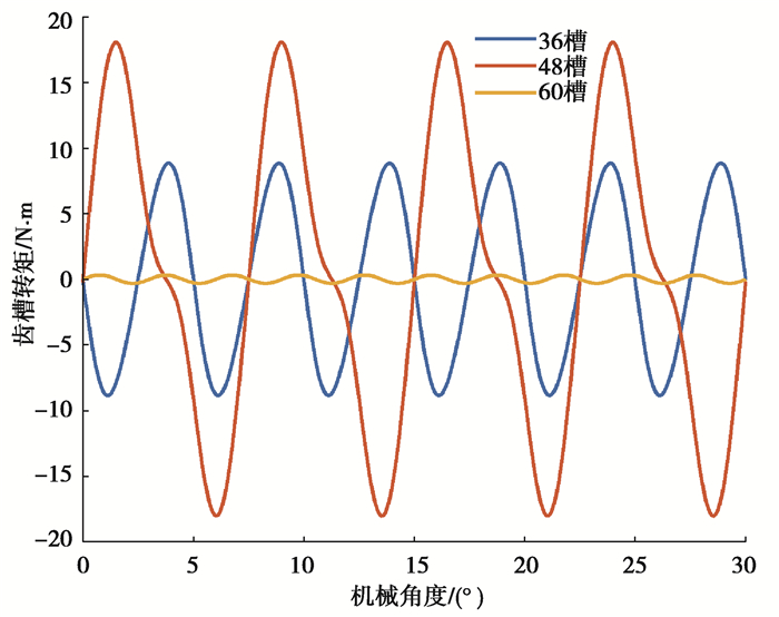
|
图 11 齿槽转矩 Fig. 11 Cogging torque |
| 表 3 齿槽转矩峰值 Table 3 Cogging torque peak |
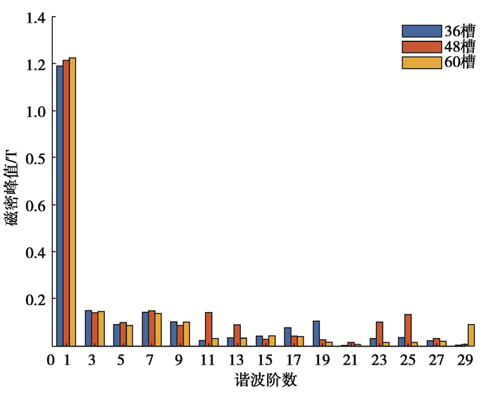
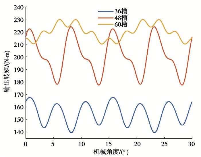
在电流为200 A的额定负载工况下,负载气隙磁密分布如图 7和图 12所示,电枢磁场和永磁体磁场耦合,径向气隙磁密波形正弦化,60槽8极电机的谐波畸变率最小,正弦性更好,如表 4所示。负载径向气隙磁密谐波分布如图 13,同空载特性相似,前9阶径向气隙磁密谐波幅值相差微小,9阶之后,60槽8极电机的径向气隙磁密谐波含量明显降低。如图 14和表 4所示,60槽8极电机相比36槽8极电机,转矩峰值提升了36.97%,转矩脉动量降低了35.22%,相比48槽8极电机,转矩峰值提升了2.59%,转矩脉动量降低了57.97%,3种极槽配合的输出转矩有较大差异原因有:60槽8极电机的径向气隙磁密分布更加正弦化,使得转矩脉动较低,其切向气隙磁密分布更加稠密,使其具有更大的输出转矩;另外,绕组分布形式的不同也对输出转矩有一定影响。
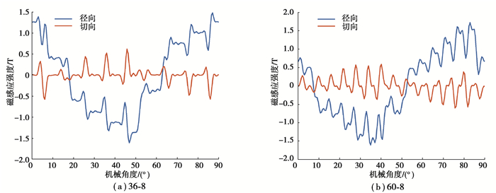
|
图 12 负载气隙磁密 Fig. 12 On-load air-gap flux density |
| 表 4 径向气隙磁密和转矩特性 Table 4 Radial air gap flux and torque characteristics |
|
图 13 负载径向气隙磁密谐波分布 Fig. 13 Harmonic spectrum of on-load radial air gap flux |
|
图 14 输出转矩 Fig. 14 Output torque |
文中选用表贴式内转子永磁同步电机作为研究对象,永磁体径向充磁,绕组采用非重叠绕组,建立了该类电机的二维解析模型,并借助有限元验证了该解析方法的正确性。文章选用了转子均为8极,定子36槽、60槽的分数槽和48槽的整数槽两类极槽配合,利用文中建立的解析模型分析计算了这3种极槽配合电机空载和负载特性。
36槽8极和60槽8极电机的齿槽转矩远小于48槽8极电机,且负载径向气隙磁密谐波畸变率分别比48槽8极低19.99%和24.73%,谐波含量少,转矩脉动量小,进一步说明分数槽配合能降低齿槽转矩,负载气隙磁密正弦性更好,有利于降低电磁噪声和转矩脉动。36槽、48槽和60槽的输出转矩依次增加,且60槽的输出转矩远大于36槽,所以在一定范围内,多槽结构有利于提升电机转矩输出。综上,60槽8极电机能更好地满足电动汽车用驱动电机性能要求。
文中建立的解析模型未考虑铁磁材料的磁饱和效应,但极槽配合选取主要参考空载和额定工况点,所以铁磁材料磁饱和影响较小,电机电磁性能和输出性能对于极槽配合的选取依旧具有非常重要的参考性,为电机的初步设计提供了更加高效便捷的方式。
| [1] |
Abdel-Khalik A S, Ahmed S, Massoud A M. A six-phase 24-slot/10-pole permanent-magnet machine with low space harmonics for electric vehicle applications[J]. IEEE Transactions on Magnetics, 2016, 52(6): 1-10. |
| [2] |
Lin F, Zuo S, Wu X D. Electromagnetic vibration and noise analysis of permanent magnet synchronous motor with different slot-pole combinations[J]. IET Electric Power Applications, 2016, 10(9): 900-908. DOI:10.1049/iet-epa.2016.0044 |
| [3] |
王晓远, 赵玉双, 高淼. 转子槽数对电动汽车用异步电机性能的影响[J]. 天津大学学报(自然科学与工程技术版), 2016, 49(5): 450-456. Wang X Y, Zhao Y S, Gao M. Effect of the number of rotor slots on the performance of asynchronous motors for electric vehicles[J]. Journal of Tianjin University (Natural Science and Engineering Technology Edition), 2016, 49(5): 450-456. (in Chinese) |
| [4] |
Liu Y, Zhu Z Q, Gan C W, et al. Comparison of optimal slot/pole number combinations in fractional slot permanent magnet synchronous machines having similar slot and pole numbers[J]. The Journal of Engineering, 2019(17): 4585-4589. |
| [5] |
Carraro E, Bianchi N, Zhang S, et al. Design and performance comparison of fractional slot concentrated winding spoke type synchronous motors with different slot-pole combinations[J]. IEEE Transactions on Industry Applications, 2018, 54(3): 2276-2284. DOI:10.1109/TIA.2018.2807382 |
| [6] |
Wang K, Zhu Z Q, Ombach G, et al. Electromagnetic performance of an 18-slot/10-pole fractional-slot surface-mounted permanent-magnet machine[J]. IEEE Transactions on Industry Applications, 2014, 50(6): 3685-3696. DOI:10.1109/TIA.2014.2316362 |
| [7] |
李灏淳, 李立毅, 于吉坤, 等. 多边形转子磁轭永磁同步电机空载气隙磁场解析计算[J]. 中国电机工程学报, 2018, 38(11): 3354-3364. Li H C, Li L Y, Yu J K, et al. Analytic calculation of No-load air-gap magnetic fields of polygonal rotor magnetic yoke permanent magnet synchronous motors[J]. Proceedings of the CSEE, 2018, 38(11): 3354-3364. (in Chinese) |
| [8] |
Yin H, Wu L J, Zheng Y T, et al. Magnetic field prediction in surface-mounted PM machines with parallel slot based on a nonlinear subdomain and magnetic circuit hybrid model[C/OL]. 2019 IEEE International Electric Machines & Drives Conference (IEMDC). New York, USA: IEEE, 2019(2019-08-05)[2019-09-25]. https://ieeexplore.ieee.org/document/8785318.
|
| [9] |
Wu L J, Yin H, Wang D, et al. A nonlinear subdomain and magnetic circuit hybrid model for open-circuit field prediction in surface-mounted PM machines[J]. IEEE Transactions on Energy Conversion, 2019, 34(3): 1485-1495. DOI:10.1109/TEC.2019.2918348 |
| [10] |
Zhu Z Q, Wu L J, Xia Z P. An accurate subdomain model for magnetic field computation in slotted surface-mounted permanent-magnet machines[J]. IEEE Transactions on Magnetics, 2010, 46(4): 1100-1115. DOI:10.1109/TMAG.2009.2038153 |
| [11] |
杨金歌, 邓兆祥, 周忆, 等. 车用永磁轮毂电机解析建模与齿槽转矩削弱[J]. 西安交通大学学报, 2018, 52(1): 84-91, 114. Yang J G, Deng Z X, Zhou Y, et al. Analytical modeling and cogging torque weakening of permanent magnet in-wheel motor for electric vehicles[J]. Journal of Xi'an Jiaotong University, 2018, 52(1): 84-91, 114. (in Chinese) |
| [12] |
张河山, 邓兆祥, 杨金歌, 等. 表贴式永磁电机磁场的解析计算与分析[J]. 汽车工程, 2018, 40(7): 850-857, 864. Zhang H S, Deng Z X, Yang J G, et al. Analytic calculation and analysis of magnetic field in surface-mounted permanent magnet motor[J]. Automotive Engineering, 2018, 40(7): 850-857, 864. (in Chinese) |
| [13] |
Oner Y, Zhu Z Q, Wu L J, et al. Analytical on-load subdomain field model of permanent-magnet vernier machines[J]. IEEE Transactions on Industrial Electronics, 2016, 63(7): 4105-4117. DOI:10.1109/TIE.2016.2532285 |
| [14] |
Djelloul-Khedda Z, Boughrara K, Dubas F, et al. Nonlinear analytical prediction of magnetic field and electromagnetic performances in switched reluctance machines[J]. IEEE Transactions on Magnetics, 2017, 53(7): 1-11. |
| [15] |
徐重鹤. 低速大转矩永磁直驱电机极槽选择问题的研究[D]. 沈阳: 沈阳工业大学, 2017. Xu C H. Research of low speed high torque permanent magnet direct driving motor's pole-slot combination[D]. Shenyang: Shenyang University of Technology, 2017. (in Chinese) |
 2021, Vol. 44


