桩基础承载力高、沉降小,能够较好地解决场地的承载问题,桩基已成为最广泛的地基加固处理技术[1],是岩土工程中的热门研究课题,其中对单桩[2]和群桩[3]的研究尤为突出。基桩的种类繁多,除了传统的圆桩和方桩,异形截面桩也广泛应用于工程中,如:X形桩[4-6]、Y形桩[7]、螺纹桩等。螺纹桩是一种新型的地基处理桩型,其桩侧摩阻力较大,极大地提高了桩基的竖向承载力[8]。在相同桩径和桩长条件下,两段式螺纹桩的单桩复合地基极限承载力相比于普通光滑桩可以提高67%[9]。螺纹桩与其他桩型相比,桩的承载力高,适应性强,桩身质量可靠,经济效益显著。
螺纹桩最初是由桩身带有螺旋叶片的螺旋桩发展而来,螺旋桩目前已得到广泛应用[10],众多学者对螺旋桩承载性能进行研究,有现场试验方法研究[11-12]、有限元方法研究[13]等。日本首先应用全螺旋预制桩,随后由Fukuei Kosan公司研发了预制钢纤维混凝土螺旋桩,但主要是通过现场载荷试验确定其极限承载力。国内对螺纹桩承载特性的研究起步较晚,吴敏等[14]指出螺纹桩的承载机理相较于普通圆桩是有差别的,他们的关系就像日常生活中的螺丝钉和钉子。李成巍等[15]通过将室内模型试验与数值模拟的结果进行分析,提出灌注螺纹桩的承载能力取决于土体的抗剪强度。通过室内模型试验,孟振等[16]指出螺纹桩的极限承载力是与其内径相同的普通圆桩的3~4倍,与其外径相同的普通圆桩的1~2倍。周杨等[17]对变截面螺纹桩与螺纹直桩进行了分析。马文杰等[18]通过对螺纹桩的研究,提出了螺纹桩竖向承载力计算公式,并对螺纹桩的桩身结构参数对螺纹桩承载力的影响进行了研究。
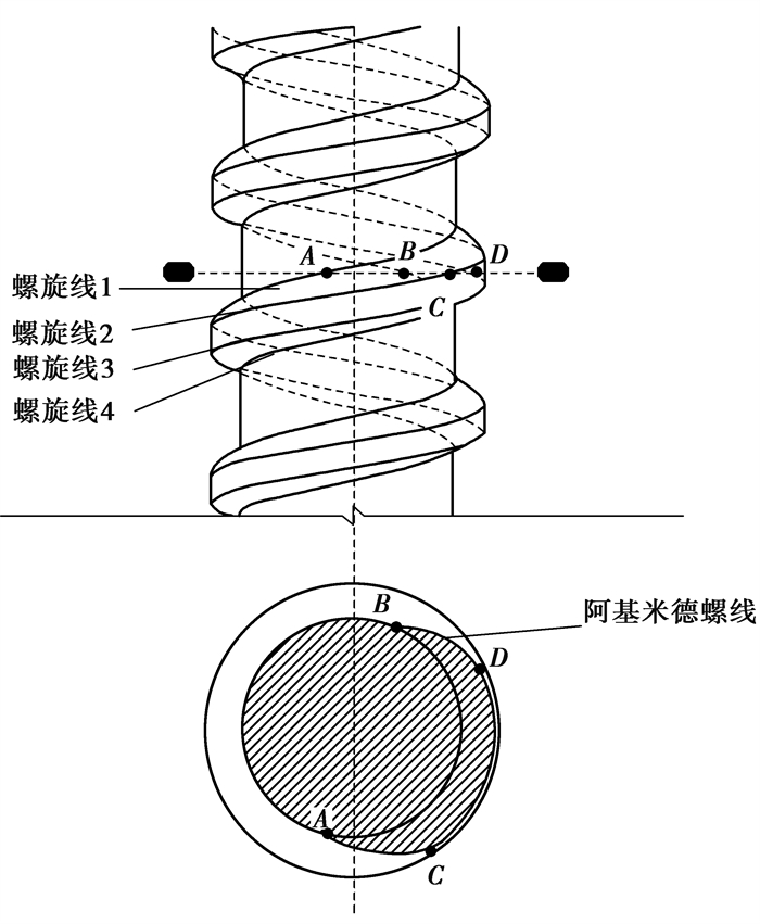
螺纹桩是在圆桩的外侧增加凸起的螺纹,也就是螺纹桩的螺牙部分,其横截面为不规则形状,如图 1所示,有些类似于圆截面,但也存在差异性。到目前为止,关于螺纹桩的截面积和周长的计算公式尚未见报道,也少有对其结构几何特性进行理论分析。然而,要在工程应用中推广螺纹桩,对其结构进行理论计算是必不可少的。文中对螺纹桩的截面进行几何解析,从理论上推导出截面的面积、周长、形心以及惯性矩的理论公式,采用控制变量的方法讨论了螺纹桩螺牙结构参数的影响,为螺纹桩受竖向和水平向荷载作用的力学特性进行数值分析提供了理论。
|
图 1 螺纹桩截及橫截面 Fig. 1 Screw pile and cross-section of screw pile |
螺牙相同的螺纹直桩和变直径的螺钉桩的截面形状是相同的,不同的是螺钉桩不同高度处截面的内径不同。根据《螺纹桩技术规程JGJ/T 379—2016》[19]中尺寸表可见,螺牙的内侧厚度大于外侧厚度,常用螺纹桩轴向剖面的螺牙轮廓是直线,可以认为,螺纹桩截面与机械中常用的阿基米德蜗杆(ZA蜗杆)[20]的齿轮部分是相似的,也就是说螺纹桩橫截面轮廓线包含阿基米德螺线[21]。阿基米德螺线是指一个点匀速离开一个固定点的同时又以固定的角速度绕该固定点转动而产生的轨迹,其极坐标方程式可表示为
| r(θ)=a+bθ, | (1) |
其中:a表示螺线起点与圆心点的距离;b表示螺旋线每增加单位角度r随之对应增加的数值,a和b的值均为实数。
螺纹桩截面的4个控制变量为螺纹桩内半径r1、螺牙间距s、螺牙高度h以及螺牙厚度t,但是螺牙内外侧厚度不同。在《螺纹桩技术规程JGJ/T 379—2016》的常用螺纹桩尺寸表中显示螺牙内侧厚度为外侧厚度的2倍或是接近于2倍,为了减少变量,文中默认螺牙内侧厚度是外侧的2倍。
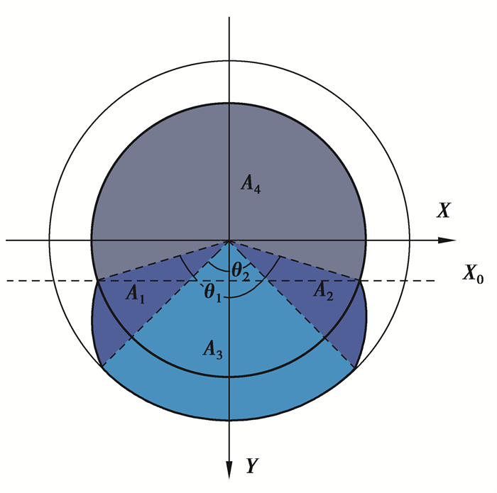
螺纹桩的任意截面形状是由2条镜面対称的阿基米德螺线以及直径为桩内径和外径的2条圆弧线的部分段组成的不规则形状,可以将其拆分为多个规则形状的组合,如图 2所示。根据图 2中A、B、C和D 4点的关系可以得到:
|
图 2 螺纹桩截面示意图 Fig. 2 Section diagram of screw pile |
| θ1=2πst, | (2) |
| θ2=πts, | (3) |
| a=r1,b=2hθ1−θ2=2hsπt, | (4) |
将式(2)、式(3)、式(4)代入式(1),并结合图 2中的坐标系,可得到阿基米德螺线的AC段的极坐标方程:
| r(θ)=r1+2hsπt(θ+π2−πts),θ∈[3π2−πts,3π2−πt2s]。 | (5) |
螺纹桩截面面积按照划分的A1、A2、A3、A4 4个区域进行计算,其中,A1和A2为2个包含阿基米德螺线的边界且镜面対称的部分,A3是半径为(r1+h)、角度为θ2的扇形,而A4是半径为r1、角度为(π-θ1) 的扇形。A1部分的面积是根据阿基米德螺线的极坐标方程进行积分运算得到。故A1区域的面积A1为
| A1=∫3π2−πt2s3π2−πt3 dA=πt6sh[(r1+h)3−r13], | (6) |
螺纹桩截面总面积A为
| A=2A1+A3+A4=2A1+πr122π−θ12π+π(r1+h)2θ22π=πt6sh[(r1+h)3−r13]+r12π(s−t)s+π(r1+h)2t2s。 | (7) |
螺纹桩截面周长同样是根据4个区域的组合进行计算的,包括阿基米德螺线长度和圆弧长度。根据阿基米德螺线极坐标方程,通过积分可得阿基米德螺线AC的长度l为
| l=1b∫r1+hr1√b2+r2 dr=1b[(12r√b2+r2+12b2ln|r+√b2+r2|+C)∣r1+hr1] 。 | (8) |
则螺纹桩截面的周长C为
| C=2l+2π(r1+h)θ22π+2πr12π−θ12π=2b[(12r√b2+r2+12b2ln|r+√b2+r2|+C)|r1+hr1]+π(ht+2r1s−r1t)s。 | (9) |
由图 2可知,螺纹桩截面为对称图形,其对称轴为过形心的Y轴,仅有1条,故Y轴即为截面的1条形心主轴。螺纹桩截面的另一条形心主轴即为过图形形心且垂直于Y轴、平行于X轴的X0轴。
设形心坐标为(0,yc),可得:
| yc=∫y dAA, | (10) |
其中,螺纹桩截面在图 2坐标系中的面积矩可分为内圆面和内圆外螺牙截面2个部分进行计算,而内圆面的面积矩为0,故截面面积矩为
| ∫y dA=∬ | (11) |
联立式(7)、式(10)、式(11)即可解得:
| y_c=\frac{2 \int_{\frac{3 {\rm{ \mathsf{π} }}-\theta_1}{2}}^{\frac{3 {\rm{ \mathsf{π} }}-\theta_2}{2}} \sin \theta \mathrm{d} \theta \int^{r_1}+b\left(\theta-\frac{3 {\rm{ \mathsf{π} }}-\theta_1}{2}\right)_{r_1} r^2 \mathrm{~d} r+2 \int_{\frac{3 {\rm{ \mathsf{π} }}-\theta_2}{2}}^{\frac{3 {\rm{ \mathsf{π} }}}{2}} \sin \theta \mathrm{d} \theta \int_{r_1}^{r_1+h} r^2 \mathrm{~d} r}{\frac{{\rm{ \mathsf{π} }} t}{6 s h}\left[\left(r_1+h\right)^3-r_1^3\right]+r_1{ }^2 \frac{{\rm{ \mathsf{π} }}(s-t)}{s}+{\rm{ \mathsf{π} }}\left(r_1+h\right)^2 \frac{t}{2 s}} 。 | (12) |
对于桩截面的惯性矩计算,在进行受力分析中关注的是截面的主惯性矩。螺纹桩截面有2条形心主轴,其主惯性矩计算公式如下:
螺纹桩截面相对于对称轴Y轴的主惯性矩Iyc为
| \begin{array}{*{20}{l}} I_{y C}=\int x^2 \mathrm{~d} A=\iint_D r^3 \cos ^2 \theta \mathrm{d} \theta \mathrm{d} r+\frac{{\rm{ \mathsf{π} }}\left(2 r_1\right)^4}{64}=\\ \;\;\;\;\;\;\;\;\;\;2\left[\int_{\frac{3 {\rm{ \mathsf{π} }}-\theta_1}{2}}^{\frac{3 {\rm{ \mathsf{π} }}-\theta_2}{2}} \cos ^2 \theta \mathrm{d} \theta \int^{r_1}+b\left(\theta-\frac{3 {\rm{ \mathsf{π} }}-\theta_1}{2}\right)_{r_1} r^3 \mathrm{~d} r+\int_{\frac{3 {\rm{ \mathsf{π} }}-\theta_2}{2}}^{\frac{3 {\rm{ \mathsf{π} }}}{2}} \cos ^2 \theta \mathrm{d} \theta \int_{r_1}^{r_1+h} r^3 \mathrm{~d} r\right]+\frac{{\rm{ \mathsf{π} }}\left(2 r_1\right)^4}{64} 。\end{array} | (13) |
螺纹桩截面相对于过形心垂直于对称轴的X0轴的主惯性矩Ixc为
| I_x=I_{x c}+m^2 {A}, | (14) |
式中,m表示X轴与X0轴的距离。
| \begin{aligned} I_{x c}=& I_x-y_c^2 A=\iint_D r^3 \sin ^2 \theta \mathrm{d} \theta \mathrm{d} r-y_c^2 A=\\ & 2 \int_{\frac{3 {\rm{ \mathsf{π} }}-\theta_1}{2}}^{\frac{3 {\rm{ \mathsf{π} }}-\theta_2}{2}} \sin ^2 \theta \mathrm{d} \theta \int_{r_1}^{r_1+b\left(\theta-\frac{3 {\rm{ \mathsf{π} }}-\theta_1}{2}\right)} r^3 \mathrm{~d} r+2 \int_{\frac{3 {\rm{ \mathsf{π} }}-\theta_2}{2}}^{\frac{3 {\rm{ \mathsf{π} }}}{2}} \sin ^2 \theta \mathrm{d} \theta \int_{r_1}^{r_1+h} r^3 \mathrm{~d} r-y_c^2 A 。\end{aligned} | (15) |
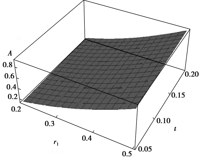
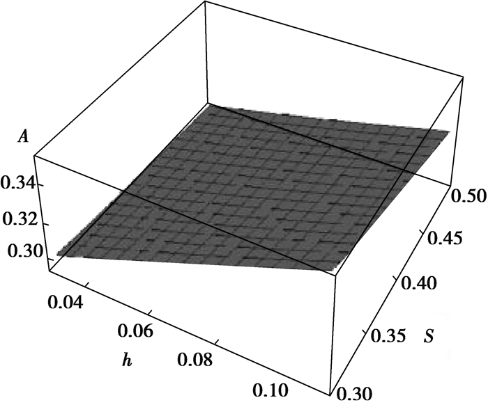
为了讨论螺纹桩截面螺纹桩内半径r1、螺牙间距s、螺牙高度h、螺牙厚度t 4个控制变量对截面几何特性的影响,根据工程应用中螺纹桩结构尺寸范围取值,分别在s、h(s=0.4 m,h=0.1 m)一定和t、r1(t=0.12 m,r1=0.3 m)一定2种情况下,采用Mathematica软件绘制三维图形,其中r1从0.2 m变化到0.5 m,t从0.05 m变化到0.2 m,s从0.3 m变化到0.5 m,h从0.03 m变化到0.11 m,并对截面的几何特性进行分析。
2.1 截面面积图 3和图 4中分别表示了螺纹桩截面面积在2种情况下的变化规律,给出了s、h、t和r1 4个控制变量对截面面积的影响。螺纹桩截面面积随着内半径、螺牙厚度和高度的增大而增大,随着螺牙间距的增大而减小。在s、h一定时,t取0.12 m,在r1的变化范围内,截面面积从0.16 m2增大到0.86 m2;r1取0.3 m,在t的变化范围内,截面面积由0.30 m2增大到0.36 m2。在t、r1一定时,h取0.1 m,在s的变化范围内,截面面积从0.35 m2减小到0.32 m2;s取0.4 m,在h的变化范围内,截面面积由0.30 m2增大到0.34 m2。内半径对截面面积的影响最为明显,内半径由0.2 m变化到0.5 m,面积增大了4.4倍。4个变量中,根据实际工程的合理性考虑,s和t的是相互影响的,t始终小于s。
|
图 3 t、r1对截面面积的影响 Fig. 3 The influence of t and r1 on cross-sectional area |
|
图 4 s、h对截面面积的影响 Fig. 4 The influence of s and h on cross-sectional area |
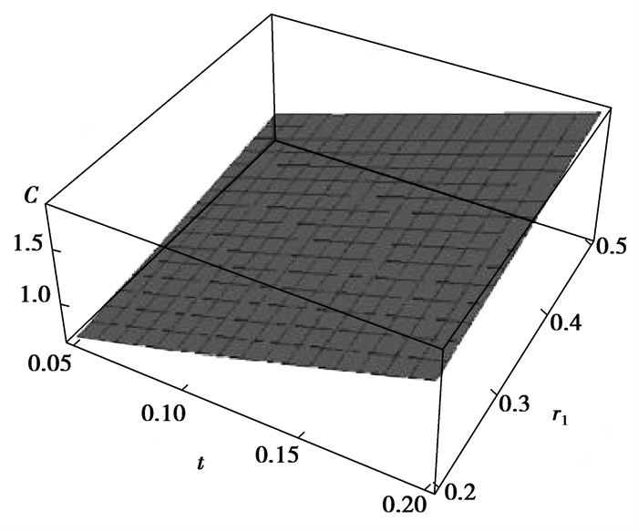
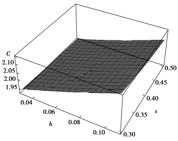
图 5和图 6分别表示了螺纹桩截面的周长在2种情况下的变化规律。螺纹桩截面周长随着内半径、螺牙厚度和高度的增大而增大,随着螺牙间距的增大而减小。在s、h一定时,t取0.12 m,在r1的变化范围内,截面周长从1.47 m增大到3.32 m;r1取0.3 m时,在t的变化范围内,截面周长从2.05 m增大到2.15 m。在t、r1一定时,h取0.1 m,在s的变化范围内,截面周长从2.12 m减小到2.07 m;s取0.4 m时,在h的变化范围内,截面周长从1.93 m增大到2.11 m。内半径对截面周长的影响最为显著,内半径由0.2 m变化到0.5 m,周长增大了1.3倍。
|
图 5 t、r1对截面周长的影响 Fig. 5 The influence of t and r1 on cross-sectional circumference |
|
图 6 s、h对截面周长的影响 Fig. 6 The influence of s and h on cross-sectional circumference |
螺纹桩截面周长与面积的比λ的计算公式如下:
| \lambda=\frac{C}{A}=\frac{\frac{2}{b}\left[\left.\left(\frac{1}{2} r \sqrt{b^2+r^2}+\frac{1}{2} \ln \left|r+\sqrt{b^2+r^2}\right|+C\right)\right|_{r_1} ^{r_1+h}\right]+\frac{{\rm{ \mathsf{π} }}\left(h t+2 r_1 s-r_1 t\right)}{s}}{\frac{{\rm{ \mathsf{π} }} t}{6 S h}\left[\left(r_1+h\right)^3-r_1^3\right]+r_1^2 \frac{{\rm{ \mathsf{π} }}(s-t)}{s}+{\rm{ \mathsf{π} }}\left(r_1+h\right)^2 \frac{t}{2 s}} 。 | (16) |
截面周长与截面积的比值实质上就是桩侧表面积与桩身体积的比值,从桩侧摩阻力的角度考虑,反映了螺纹桩桩身材料的利用效率情况,是工程应用中评价螺纹桩经济效益的重要指标。
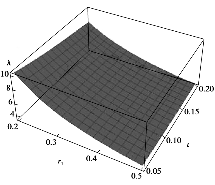
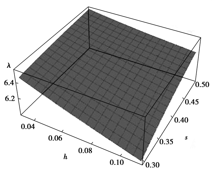
图 7、图 8分别表示了螺纹桩截面周长与面积之比λ的变化规律。螺纹桩截面周长与面积比λ随着内半径、螺牙厚度和高度的增大而减小,随着螺牙间距的增大而增大。在s、h一定时,t取0.12 m,在r1的变化范围内,截面周长与面积比λ从9.19减小到3.85;r1取0.3 m时,在t的变化范围内,截面周长与面积比λ从6.76减小到5.92。在t、r1一定时,h取0.1 m,在s的变化范围内,截面周长与面积比λ从6.09增大到6.42;s取0.4 m时,在h的变化范围内,截面周长与面积比λ从6.53减小到6.25。在4个控制变量的影响下,周长与面积的比λ与面积和周长的变化规律相反,因为4个控制变量对截面面积的影响要大于周长。
|
图 7 t、r1对λ的影响 Fig. 7 The influence of t and r1 on λ |
|
图 8 s、h对λ的影响 Fig. 8 The influence of s and h on λ |
相同截面积的螺纹桩与圆桩周长比η的计算公式如下:
| \eta=\frac{C_s}{C_o}=\frac{\frac{2}{b}\left[\left.\left(\frac{1}{2} r \sqrt{b^2+r^2}+\frac{1}{2} \ln \left|r+\sqrt{b^2+r^2}\right|+C\right)\right|_{r_1} ^{r_1+h}\right]+\frac{{\rm{ \mathsf{π} }}\left(h t+2 r_1 s-r_1 t\right)}{s}}{2 {\rm{ \mathsf{π} }} \sqrt{\frac{t}{6 S h}\left[\left(r_1+h\right)^3-r_1^3\right]+r_1^2 \frac{(s-t)}{s}+\left(r_1+h\right)^2 \frac{t}{2 s}}} 。 | (17) |
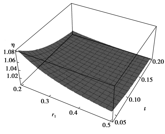
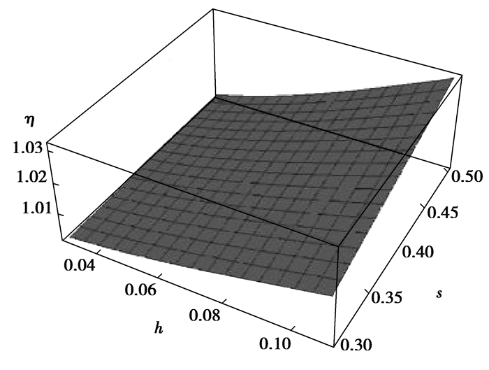
从图 9、图 10可以发现,在相同的截面面积的情况下,螺纹桩与圆桩截面周长比η随着内半径和螺牙厚度的增大而减小,随着螺牙高度和间距的增大而增大。在s、h一定时,t取0.12 m,在r1的变化范围内,截面周长比η从1.04减小到1.01;r1取0.3 m时,在t的变化范围内,截面周长比η从1.05减小到1.01。在t、r1一定时,h取0.1 m,在s的变化范围内,截面周长比η从1.01增大到1.03;s取0.4 m时,在h的变化范围内,截面周长比η从1.00增大到1.02。可以看出,在相同截面面积情况下,螺纹桩的截面周长比圆桩大1%~5%,所以相同混凝土用量下,螺纹桩周长略大于圆桩。
|
图 9 t、r1对η的影响 Fig. 9 The influence of t and r1 on η |
|
图 10 s、h对η的影响 Fig. 10 The influence of s and h on η |
相同截面周长的螺纹桩与圆桩的面积比γ的计算公式如下:
| \gamma=\frac{A_s}{A_o}= \frac{\frac{8 {\rm{ \mathsf{π} }}^3 t\left[\left(r_1+h\right)^3-r_1^3\right]}{3 s h}+\frac{4 r_1^2 {\rm{ \mathsf{π} }}^2(s-t)}{s}+\frac{2 {\rm{ \mathsf{π} }}^2\left(r_1+h\right)^2 t^2}{s}} {\left(\begin{array}{c} \frac{{\rm{ \mathsf{π} }} t\left(r_1+h\right) \sqrt{\left(\frac{2 h s}{{\rm{ \mathsf{π} }} t}\right)^2+\left(r_1+h\right)^2}}{2 h s}-\frac{{\rm{ \mathsf{π} }} t r_1 \sqrt{\left(\frac{2 h s}{{\rm{ \mathsf{π} }} t}\right)^2+r_1^2}}{2 h s} \\ +\frac{2 h s}{{\rm{ \mathsf{π} }} t} \ln \left[\frac{\left(r_1+h\right)+\sqrt{\left(\frac{2 h s}{{\rm{ \mathsf{π} }} t}\right)^2+\left(r_1+h\right)^2}}{r_1+\sqrt{\left(\frac{2 h s}{{\rm{ \mathsf{π} }} t}\right)^2+r_1^2}}\right]+\frac{{\rm{ \mathsf{π} }}\left(h t+2 r_1 s-r_1 t\right)}{s} \end{array}\right)^2}。 | (18) |
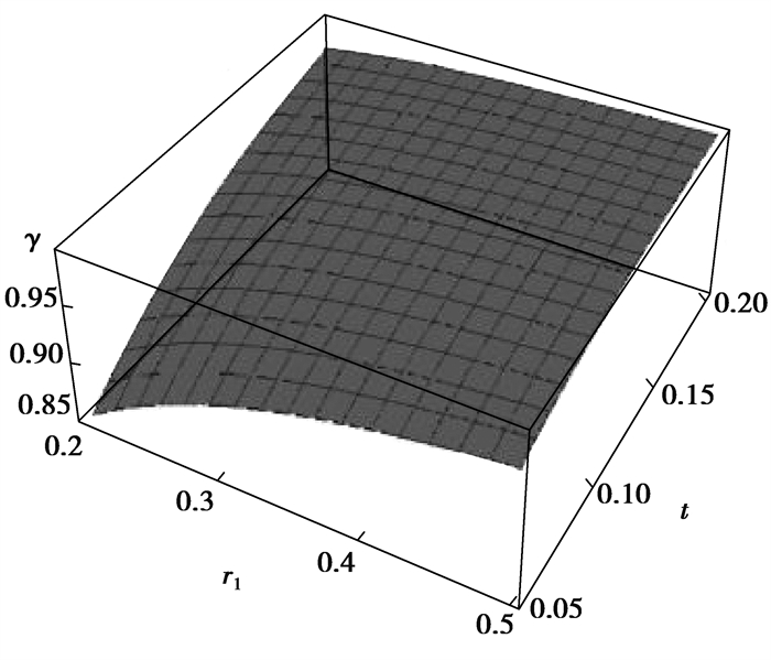
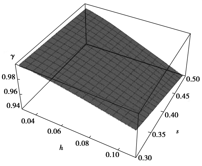
在截面周长相等的情况下,螺纹桩与圆桩的面积比γ的变化规律,如图 11和图 12所示。螺纹桩与圆桩截面面积比γ随着内半径和螺牙厚度的增大而增大,随着间距和螺牙高度的增大而减小。在s、h一定时,t取0.12 m,在r1的变化范围内,截面面积比γ从0.93增大到0.98;r1取0.3 m时,在t的变化范围内,截面面积比γ从0.91增大到0.98。在t、r1一定时,h取0.1m,在s的变化范围内,截面面积比γ从0.97减小到0.95;s取0.4 m时,在h的变化范围内,截面面积比γ从0.99减小到0.95。可以看出,在相同截面周长情况下,螺纹桩的截面面积比圆桩小1%~9%。
|
图 11 t、r1对γ的影响 Fig. 11 The influence of t and r1 on γ |
|
图 12 s、h对γ的影响 Fig. 12 The influence of s and h on γ |
在螺纹柱结构4个控制变量的影响下,研究了截面形心的位置变化,分析了螺纹桩截面惯性矩的变化规律,并将螺纹桩与圆桩的惯性矩进行了对比分析。
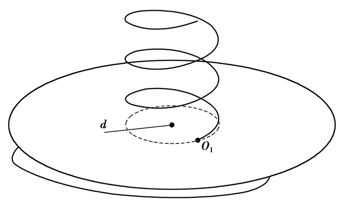
3.1 截面形心螺纹桩的纵截面为非对称图形,在任意高度处的横截面形状是相同的。螺纹桩是由其横截面图形在高度范围内不停地绕着其内圆的圆心O匀速旋转,在高度方向匀速运动而形成的柱体结构。如图 13所示,O1点是螺纹桩横截面的形心位置。根据螺纹桩的柱体结构形成过程可知,螺纹桩所有横截面的形心O1在其柱体结构内的轨迹是一条以d为半径,s为间距的螺旋线,且O1的轨迹在截面平面内的投影为以d为半径的圆。
|
图 13 形心轨迹示意图 Fig. 13 Diagram of centroid trajectory |
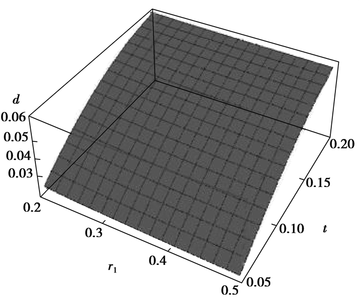
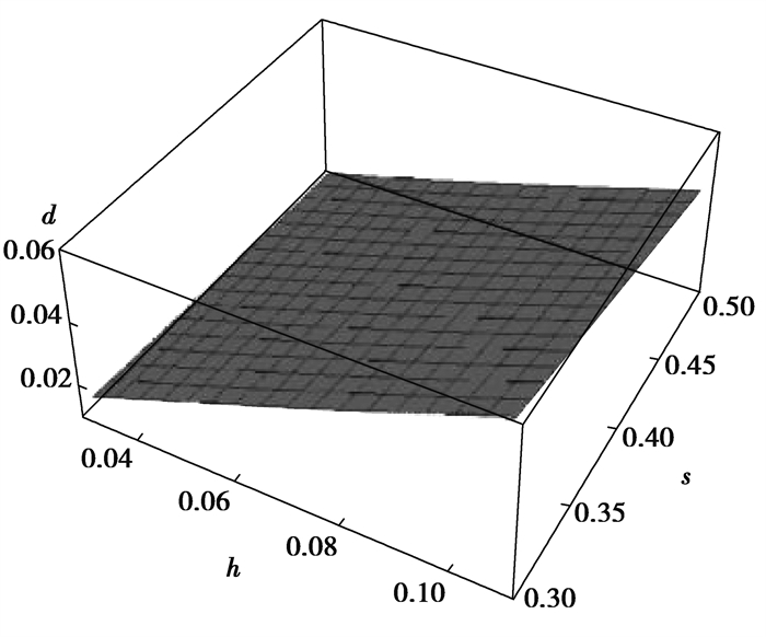
从式(12)可以看出,截面形心的位置受螺纹桩结构的4个控制变量的影响。通过分析图 14和图 15可以发现,螺纹桩横截面形心位置与内圆圆心的距离d随着螺牙厚度和高度的增大而增大,随着内半径和螺纹间距的增大而减小。
|
图 14 t、r1对d的影响 Fig. 14 The influence of t and r1 on d |
|
图 15 s、h对d的影响 Fig. 15 The influence of s and h on d |
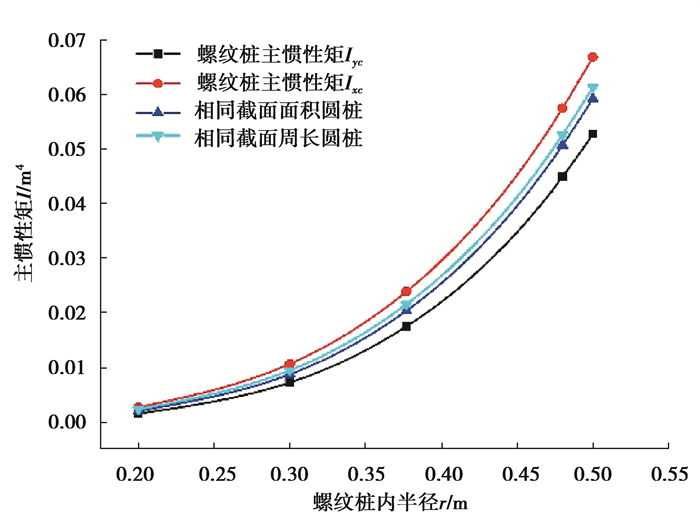
螺纹桩截面不同于普通的圆桩、方桩以及X型桩等,2个主惯性矩Iyc、Ixc的数值大小不同,其中Ixc总是大于Iyc。在文中分析的参数范围内,Ixc比Iyc高13%~72%。相较于圆桩,主惯性矩Iyc较小,主惯性矩Ixc较大。从图 16~图 19可以看出,螺纹桩主惯性矩随着内半径、螺牙厚度和高度的增大而增大,随着螺牙间距的增大而减小。
|
图 16 螺纹桩与圆桩主惯性矩受内半径影响的变化规律 Fig. 16 The changes of the main inertia moment of screw pile and circular pile affected by the radius of screw pile |
|
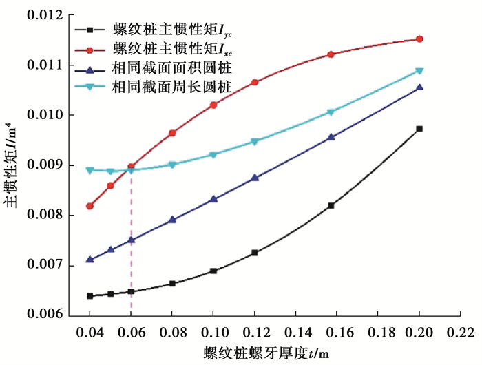
图 17 螺纹桩与圆桩主惯性矩受螺牙厚度影响的变化规律 Fig. 17 The changes of the main inertia moment of screw pile and circular pile affected by the thickness of screw thread |
|
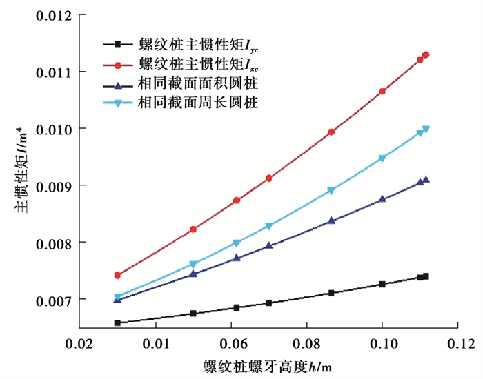
图 18 螺纹桩与圆桩主惯性矩受螺牙高度影响的变化规律 Fig. 18 The changes of the main inertia moment of screw pile and circular pile affected by the height of screw thread |
|
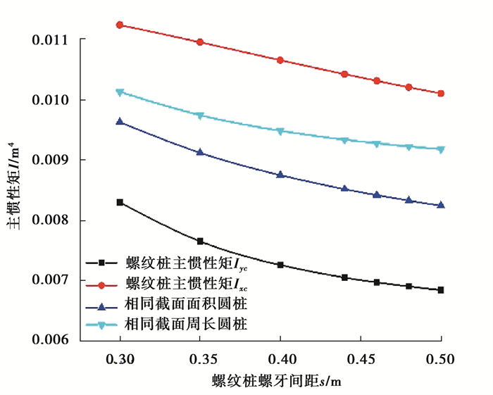
图 19 螺纹桩与圆桩主惯性矩受螺牙间距影响的变化规律 Fig. 19 The changes of the main inertia moment of screw pile and circular pile affected by the screw pitch |
由图 16可知,螺纹桩和圆桩的主惯性矩随着内半径的增大呈指数型增大。相同截面积和相同截面周长的圆桩惯性矩在内半径的影响下变化规律相近,数值大小始终在螺纹桩两主惯性矩值之间。当内半径在0.2~0.5 m范围内时,主惯性矩Ixc比主惯性矩Iyc高27%~72%,Ixc比相同截面面积圆桩高13%~33%,比相同截面周长圆桩高9%~14%。
由图 17可知,在螺牙厚度的影响下,螺纹桩主惯性矩Ixc随螺牙厚度的增大速率减小,而主惯性矩Iyc随螺牙厚度的增大速率增大。所以,存在1个螺牙厚度的较小值和1个较大值使主惯性矩Ixc与主惯性矩Iyc相等。此时,相当于是没有螺牙结构的圆桩,螺纹桩主惯性矩Ixc、螺纹桩主惯性矩Iyc和相同截面积圆桩这3条曲线相交于这两点。其中,相同截面周长的圆桩惯性矩与螺纹桩主惯性矩Ixc对比发现,当螺牙厚度较大时,螺纹桩主惯性矩Ixc较大,此时螺纹桩截面积的分布距主轴较远而占优势;当螺牙厚度较小时,螺纹桩截面中因螺牙产生的异形区域面积减小而逐渐趋于圆形截面,而且相同截面周长圆桩的面积比螺纹桩大,此时截面积较大的圆桩惯性矩较大,在螺牙厚度t=0.06 m附近两者相等。
由图 18可知,螺纹桩主惯性矩Ixc、相同截面周长圆桩的惯性矩、相同截面积圆桩的惯性矩和螺纹桩主惯性矩Iyc,均随螺牙高度的增大线性增大,其线性斜率依次减小。由图 19可知,随着螺牙间距的变化,螺纹桩和圆桩惯性矩的变化情况几乎一致,呈线性减小的趋势,其线性变化斜率较小。可以发现,在螺牙高度和间距分别影响下,圆桩惯性矩始终介于螺纹桩两主惯性矩之间。
4 结论文中通过理论推导,建立了螺纹桩截面面积、周长、惯性矩等计算公式,探讨了截面参数对几何特性的影响规律,得到如下结论:
1) 螺纹桩截面面积和周长都随内半径、螺牙的厚度和高度的增大而增大,随螺牙间距的增大而减小。其中,内半径对截面面积和周长的影响最为明显。当内半径由0.2 m变化到0.5 m,面积增大了4.4倍,周长增大了1.3倍。
2) 螺纹桩截面周长与面积的比值λ随内半径、螺牙的厚度和高度的增大而减小,随螺牙间距的增大而增大,与面积和周长的变化规律相反,因为4个控制变量对截面面积的影响大于周长。在内半径范围,比值λ从9.19减小到3.8;在厚度范围,比值λ从6.76减小到5.92;在间距范围,比值λ从6.09增大到6.42;在高度范围,比值λ从6.53减小到6.25。
3) 螺纹桩与圆桩相比,在各个控制变量的单一影响下,相同截面面积时的周长比为1.00~1.05,相同截面周长时的面积比为0.91~0.99。所以,在相同桩截面周长和桩长时,螺纹桩的混凝土用量比圆桩少1%~9%。
4) 螺纹桩截面存在2个大小不同的主惯性矩Iyc和Ixc,Ixc总是大于Iyc,在文中分析的参数范围内,Ixc比Iyc高13%~72%。2主惯性矩随螺纹桩内半径指数增大,随螺牙厚度以相反趋势增大,随螺牙高度线性增大,随螺牙间距线性减小。相较于圆桩,主惯性矩Iyc较小,主惯性矩Ixc较大,但当螺牙厚度小于0.06 m时主惯性矩Ixc小于相同截面周长圆桩惯性矩。
从螺纹桩与圆桩的几何特性对比分析来看,相同混凝土用量下,螺纹桩的周长仅仅比圆桩大0~5%,根据已有的试验表明,桩侧螺纹大大增加了桩土界面咬合力,螺纹桩的承载力要比圆桩大很多。文中通过几何分析推导出螺纹桩的面积、周长、惯性矩等的理论公式,有助于后续进一步对螺纹桩截面受到水平或竖直荷载作用的力学特性进行理论分析,在一定程度上促进了螺纹桩的工程应用。笔者后续将基于文中研究,进一步探究螺纹截面以及桩土界面的力学性能。
| [1] |
程麦理. 黄土场地桩基横向力学行为数值模拟[J]. 工程力学, 2019, 36(S1): 229-233. Cheng M L. Numerical simulation of transverse mechanical behavior of pile foundation in loess site[J]. Engineering Mechanics, 2019, 36(S1): 229-233. (in Chinese) |
| [2] |
Ding X M, Luan L B, Zheng C J, et al. An analytical solution for wave propagation in a pipe pile with multiple defects[J]. Acta Mechanica Solida Sinica, 2020, 33(2): 251-267. DOI:10.1007/s10338-019-00123-5 |
| [3] |
Luan L B, Ding X M, Zheng C J, et al. Dynamic response of pile groups subjected to horizontal loads[J]. Canadian Geotechnical Journal, 2020, 57(4): 469-481. DOI:10.1139/cgj-2019-0031 |
| [4] |
刘汉龙, 刘芝平, 王新泉. 现浇X型混凝土桩截面几何特性研究[J]. 中国铁道科学, 2009, 30(1): 17-23. Liu H L, Liu Z P, Wang X Q. Study on the geometric characteristics of the cast-in-place X-type vibro-pile section[J]. China Railway Science, 2009, 30(1): 17-23. (in Chinese) DOI:10.3321/j.issn:1001-4632.2009.01.004 |
| [5] |
吕亚茹, 丁选明, 刘汉龙, 等. X形桩桩土相互作用对截面形状的力学响应[J]. 岩土力学, 2015, 36(S2): 357-364. Lyu Y R, Ding X M, Liu H L, et al. Mechanical response of pile-soil interactions of X-section cast-in-place concrete piles to cross-sectional shape[J]. Rock and Soil Mechanics, 2015, 36(S2): 357-364. (in Chinese) |
| [6] |
Zhou H, Yuan J R, Liu H L, et al. Analytical model for evaluating XCC pile shaft capacity in soft soil by incorporating penetration effects[J]. Soils and Foundations, 2018, 58(5): 1093-1112. DOI:10.1016/j.sandf.2018.04.005 |
| [7] |
Ren L W, Guo W D, Yang Q W. Analysis on bearing performance of Y-shaped piles under compressive and tensile loading[J]. Proceedings of the Institution of Civil Engineers-Geotechnical Engineering, 2020, 173(1): 58-69. DOI:10.1680/jgeen.18.00244 |
| [8] |
窦德功, 鲁子爱. 螺纹桩承载性状分析与研究[J]. 水运工程, 2012(4): 32-35, 43. Dou D G, Lu Z A. Bearing behavior of screw pile[J]. Port & Waterway Engineering, 2012(4): 32-35, 43. (in Chinese) DOI:10.3969/j.issn.1002-4972.2012.04.007 |
| [9] |
Jiang P C, Xu W, Zhang Y J. Analysis of the bearing behaviour of a screw-pile foundation in silt soil[J]. Proceedings of the Institution of Civil Engineers-Ground Improvement, 2019, 172(4): 257-263. DOI:10.1680/jgrim.18.00055 |
| [10] |
Ali O K, Abbas H O. Performance assessment of screw piles embedded in soft clay[J]. Civil Engineering Journal, 2019, 5(8): 1788-1798. DOI:10.28991/cej-2019-03091371 |
| [11] |
Guo Z Y, Deng L J. Field behaviour of screw micropiles subjected to axial loading in cohesive soils[J]. Canadian Geotechnical Journal, 2018, 55(1): 34-44. DOI:10.1139/cgj-2017-0109 |
| [12] |
Lanyi Bennett S A, Deng L J. Axial load testing of helical pile groups in glaciolacustrine clay[J]. Canadian Geotechnical Journal, 2019, 56(2): 187-197. DOI:10.1139/cgj-2017-0425 |
| [13] |
Kurian N P, Shah S J. Studies on the behaviour of screw piles by the finite element method[J]. Canadian Geotechnical Journal, 2009, 46(6): 627-638. DOI:10.1139/T09-008 |
| [14] |
吴敏, 李波扬. 全螺旋灌注桩: 螺纹桩竖向承载力初探[J]. 武汉大学学报(工学版), 2002, 35(5): 109-112. Wu M, Li B Y. Primary discussion on vertical load bearing capacity of screwed filling piles[J]. Engineering Journal of Wuhan University, 2002, 35(5): 109-112. (in Chinese) |
| [15] |
李成巍, 陈锦剑, 吴琼, 等. 灌注螺纹桩承载机理与计算方法[J]. 上海交通大学学报, 2010, 44(6): 726-730. Li C W, Chen J J, Wu Q, et al. Bearing mechanism and calculation method of screw pile[J]. Journal of Shanghai Jiao Tong University, 2010, 44(6): 726-730. (in Chinese) DOI:10.3969/j.issn.1674-8115.2010.06.028 |
| [16] |
孟振, 陈锦剑, 王建华, 等. 砂土中螺纹桩承载特性的模型试验研究[J]. 岩土力学, 2012, 33(S1): 141-145. Meng Z, Chen J J, Wang J H, et al. Study of model test on bearing capacity of screw piles in sand[J]. Rock and Soil Mechanics, 2012, 33(S1): 141-145. (in Chinese) |
| [17] |
周杨, 肖世国, 徐骏, 等. 变截面螺纹桩竖向承载特性试验研究[J]. 岩土力学, 2017, 38(3): 747-754, 783. Zhou Y, Xiao S G, Xu J, et al. Model test on vertical bearing capacity of variable cross-section thread piles[J]. Rock and Soil Mechanics, 2017, 38(3): 747-754, 783. (in Chinese) |
| [18] |
马文杰, 王博林, 王旭, 等. 螺纹桩承载特性的初步探讨[J]. 建筑结构, 2018, 48(S1): 738-741. Ma W J, Wang B L, Wang X, et al. Preliminary study on load characteristics of thread pile[J]. Building Structure, 2018, 48(S1): 738-741. (in Chinese) |
| [19] |
中华人民共和国住房和城乡建设部. 螺纹桩技术规程: JGJ/T 379—2016[S]. 北京: 中国建筑工业出版社, 2016. Ministry of Housing and Urban-Rural Development of the People's Republic of China. Technical specification for screw concrete pile: JGJ/T 379—2016[S]. Beijing: China Architecture & Building Press, 2016. (in Chinese) |
| [20] |
曹文钢, 李辉. 基于特征的阿基米德蜗杆(ZA)的参数化造型设计[J]. 机床与液压, 2006, 34(2): 207-208, 222. Cao W G, Li H. Using pro/E to realize the parameterized designing of Archimedes worms[J]. Machine Tool & Hydraulics, 2006, 34(2): 207-208, 222. (in Chinese) |
| [21] |
希思 T.L., 朱恩宽, 李文铭. 阿基米德全集[M]. 西安: 陕西科学技术出版社, 1998. heath T.L., Zhu E K, Li W M. The complete works of Archimedes[M]. Xi'an: Shaanxi Science and Technology Press, 1998. (in Chinese) |
 2022, Vol. 45


