2. 郑州机械研究所有限公司, 郑州 450052;
3. 中国科学院深圳先进技术研究院, 广东 深圳 518055
2. Zhengzhou Research Institute of Mechanical Engineering Co. Ltd., Zhengzhou 450052, P. R. China;
3. Shenzhen Institute of Advanced Technology, Chinese Academy of Sciences, Shenzhen, Guangdong 518055, P. R. China
与采用渐开线齿形的谐波减速器相比,双圆弧齿形谐波减速器具有承载能力大、啮合齿数多、扭转刚度高、啮合侧隙小、传动精度高等特点,在工业机器人、医疗器械与航空航天等领域得到了广泛应用[1-3]。然而插刀有效长度短且难以预估,刚轮的生产成本高,试切次数多,因此在分析刃磨后插刀加工精度的基础上,通过优化砂轮齿形与插刀齿数,延长插刀有效长度,对减少试切次数、降低刚轮生产成本具有重要意义。
谐波减速器的刚柔轮的齿形与结构参数对谐波减速器啮合性能至关重要。辛洪兵[3-4]利用改进的运动学法研究了谐波齿轮传动啮合原理,提出了双圆弧谐波减速器插齿刀的设计方法;陈晓霞等[5-6]提出了新的双圆弧谐波减速器设计方法,研究了其参数变化对刚柔轮啮合间隙的影响,并建立了谐波减速器柔轮齿圈有限元模型,分析了周向应力随齿根倒圆的变化规律;董慧敏等[7]提出了基于轮齿瞬心线的双圆弧齿形设计方法,从理论上避免了谐波传动齿顶干涉,提高了谐波减速器的啮合性能;杜雪松等[8]根据描述谐波减速器刚柔轮之间复杂空间运动关系的三维数学模型,扩展了共轭齿廓区域1.21倍;宋朝省等[9]基于支撑函数建立了谐波减速器的波发生器轮廓数学模型,通过有限元方法,分析了波发生器轮廓对谐波减速器柔轮与波发生器的装配应力;姜歌东等[10]提出了基于谐波减速器刚柔轮齿形的双圆弧双向共轭设计方法,实现了谐波减速器的多点啮合,降低了谐波减速器的啮合力,提高了谐波减速器的使用寿命。
同时,国内外学者针对谐波减速器刚轮加工制造进行了相关研究。Lai等[11]通过系统化的CAD/CAM几何造型技术,缩短了插齿刀的设计周期,提高了插齿刀的加工精度;Yamazaki等[12-13]对非渐开线小齿轮刀具的设计和制造方法进行了精确的分析,研究了刃磨量与刀具齿廓误差之间的关系;Kawalec等[14]建立了螺旋齿插齿加工数学模型,通过有限元分析的方法,增强了齿根强度;Lin等[15]讨论了渐开线插齿刀的设计原理和模型,提出了反包络法等刀具设计方法,提高了插削刀具的精度和寿命;Máté等[16]推导了插齿刀前刀面的理论刃形,提出了一种消除插刀理论误差的设计方法,减小了刃磨后插刀的加工误差,提高了插刀的使用寿命;景艳等[17]建立了双圆弧刚轮插刀齿面数学模型,揭示了双圆弧插刀结构参数对插刀可刃磨长度与加工精度的影响规律;李佳等[18]通过齿廓共轭理论,提出了无理论刃形误差插刀设计方法,从理论上完全消除了插刀的加工误差,但未考虑磨削插刀的过程。
综上所述,针对双圆弧谐波减速器刚柔轮结构参数与插齿刀的齿形设计方法已较为成熟。但针对刃磨后的插刀加工误差、插刀有效长度分析与延长的研究较少。
笔者从双圆弧谐波减速器刚轮齿形出发,采用运动学法,建立了插刀加工仿真数学模型,推导了插刀理论齿形,计算了刃磨多次后,插刀加工出刚轮的齿形误差,以3 μm刚轮齿形误差为标准,确定了插刀的有效长度;将插刀理论齿形作为插刀等效齿形,优化了插刀原始截面齿形的设计方法,延长了插刀的有效长度。
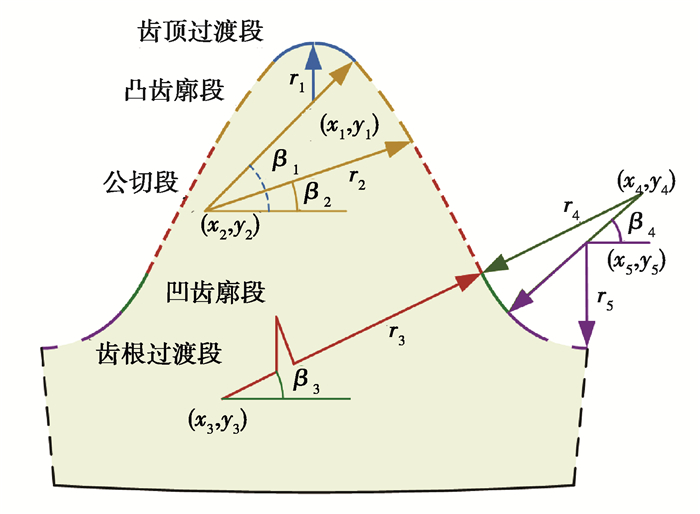
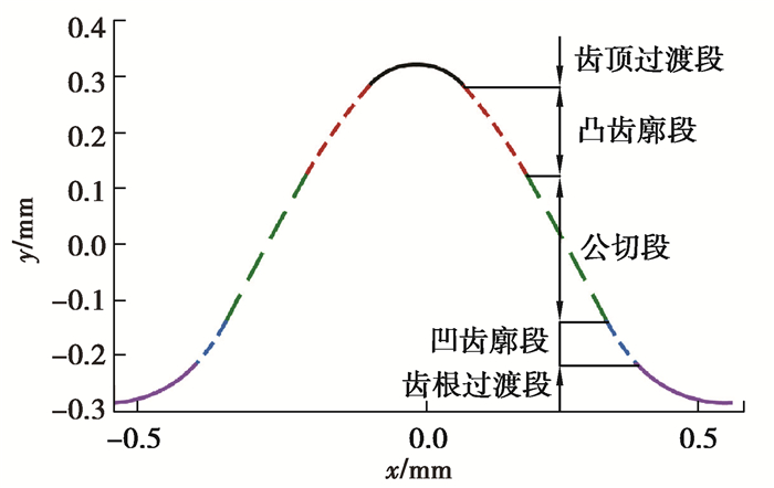
1 双圆弧插齿刀齿面建模 1.1 双圆弧谐波减速器刚轮齿廓数学模型以一款采用双圆弧齿形的谐波减速器为例,其刚轮齿数zr=102,模数m=0.25,齿形如图 1所示,由齿顶过渡段、凸齿廓段、公切段、凹齿廓段、齿根过渡段5部分组成,各齿廓段之间相切。刚轮各段圆心坐标如表 1所示。
|
图 1 双圆弧刚轮齿廓 Fig. 1 Tooth profile of the circular spline |
| 表 1 刚轮各段齿廓圆心坐标 Table 1 The center coordinates of each tooth profile of the circular spline |
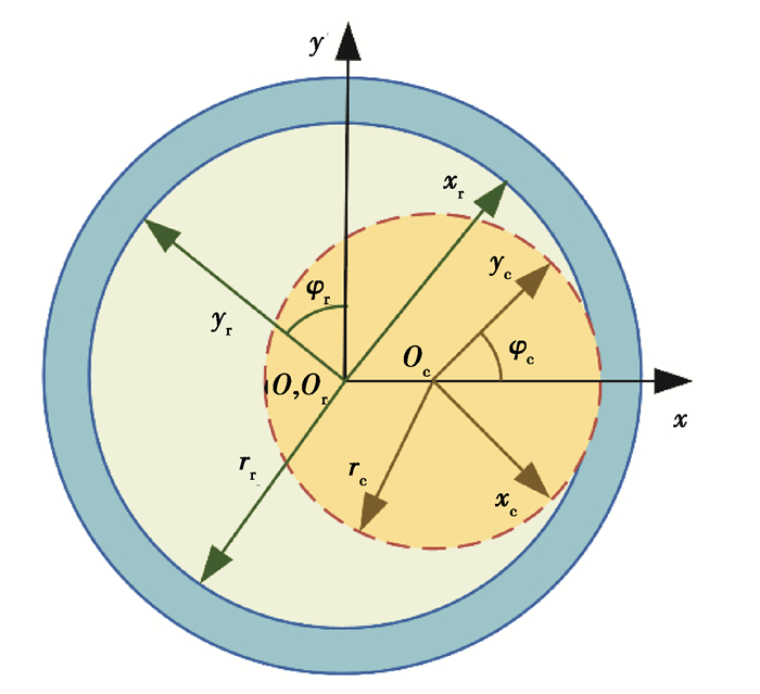
参考双圆弧谐波减速器柔轮齿廓的建模方法[19],在与刚轮固连且原点和刚轮回转中心重合的坐标系Sr(xroryr)中。
以下为刚轮各段齿廓的参数方程。
齿顶过渡段
| $ \left\{\begin{aligned} u & \in\left(0, \frac{\pi}{2}-\beta_1\right), \\ \beta_1 & =\tan -1 \frac{y_1-y_2}{x_1-x_2}, \\ x & =x_1+r_1 \sin u, \\ y & =y_1+r_1 \cos u, \end{aligned}\right. $ | (1) |
式中:r1为齿顶过渡段圆弧半径;x1为齿顶过渡段圆心横坐标;y1为齿顶过渡段圆心纵坐标。
凸齿廓段
| $ \left\{\begin{array}{l} u \in\left(0, \beta_1-\beta_2\right), \\ \beta_2=\tan -1 \frac{y_3-y_2}{x_3-x_2}, \\ x=x_2+r_2 \cos \left(u+\beta_2\right), \\ y=y_2+r_2 \sin \left(u+\beta_2\right), \end{array}\right. $ | (2) |
式中:r2为凸齿廓段圆弧半径;x2为凸齿廓段圆心横坐标;y2为凸齿廓段圆心纵坐标。
公切段
| $ \left\{\begin{array}{l} u \in\left(0, \beta_2-\beta_3\right), \\ \beta_3=\tan ^{-1} \frac{y_3-y_4}{x_3-x_4}, \\ x=x_3+r_3 \cos \left(u+\beta_3\right), \\ y=y_3+r_3 \sin \left(u+\beta_3\right) 。\end{array}\right. $ | (3) |
式中:r3为公切段圆弧半径;x3为公切段圆心横坐标;y3为公切段圆心纵坐标。
凹齿廓段
| $ \left\{\begin{array}{l} u \in\left(0, \beta_4-\beta_3\right), \\ \beta_4=\tan -1 \frac{y_4-y_5}{x_4-x_5}, \\ x=x_4-r_4 \sin \left(\frac{\pi}{2}-\beta_4+u\right), \\ y=y_4-r_4 \cos \left(\frac{\pi}{2}-\beta_4+u\right), \end{array}\right. $ | (4) |
式中:r4为凹齿廓段圆弧半径;x4为凹齿廓段圆心横坐标;y4为凹齿廓段圆心纵坐标。
齿根过渡段
| $ \left\{\begin{array}{l} u \in\left(0, \frac{\pi}{2}-\beta_4\right), \\ x=x_5-r_5 \sin u, \\ y=y_5-r_5 \cos u, \end{array}\right. $ | (5) |
式中:r5为齿根过渡段圆弧半径;x5为齿根过渡段圆心横坐标;y5为齿根过渡段圆心纵坐标。
1.2 插削加工数学仿真模型建立与插齿刀固连且原点与插刀回转中心重合的坐标系Sc(xcocyc)、固定坐标系S(xoy),结合与刚轮固连的坐标系Sr(xroryr),构成了插削加工数学仿真坐标系,如图 2所示。
|
图 2 插削加工坐标系定义 Fig. 2 Coordinate system of the simulation model of slotting the circular spline |
在刚轮的插削过程中,刚轮每转过φr时,插齿刀转动φc,二者的中心距为
| $ e_{\mathrm{c}}=r_{\mathrm{r}}-r_{\mathrm{c}} \text {, } $ | (6) |
式中:rc为刚轮半径;rr为插齿刀半径。
刚轮与插齿刀的啮合方程为
| $ \boldsymbol{n}_{\mathrm{r}} \cdot \boldsymbol{V}_{\mathrm{r}}^{\mathrm{cr}}=0, $ | (7) |
式中:nr刚轮齿廓法向量;Vrcr为刚轮坐标系中插齿刀与刚轮的相对速度。
其中插刀转角φc与刚轮转角φr的关系为
| $ \left\{\begin{array}{l} i_{\mathrm{cg}}=\frac{\varphi_{\mathrm{c}}}{\varphi_{\mathrm{r}}}=\frac{z_{\mathrm{r}}}{z_{\mathrm{c}}}, \\ \varphi=\varphi_{\mathrm{c}}-\varphi_{\mathrm{r}}, \end{array}\right. $ | (8) |
式中:icg为刚轮与插齿刀的传动比;zr为刚轮齿数;zc为插齿刀齿数。
在与刚轮固连的坐标系Sr(xroryr)中,刚轮的齿廓的位置矢量为
| $ \boldsymbol{p}_{\mathrm{r}}=x_{\mathrm{r}} \boldsymbol{i}_{\mathrm{r}}+y_{\mathrm{r}} \boldsymbol{j}_{\mathrm{r} 。} $ | (9) |
联立公式(7)(9),齿廓上满足两者的点就是啮合点。通过坐标变换将啮合点由刚轮坐标系Sr(xroryr)转换至插齿刀固连的坐标系Sr(xroryr)中,则插齿刀齿廓为
| $ \boldsymbol{p}_{\mathrm{c}}=\boldsymbol{m}_{\mathrm{cr}} \cdot \boldsymbol{p}_{\mathrm{r}} \text { 。} $ | (10) |
由坐标系Sr(xroryr)到Sc(xcocyc)的坐标转换矩阵mcr为
| $ \left[\begin{array}{ccc} \cos \varphi & \sin \varphi & -e_{\mathrm{c}} \sin \varphi_{\mathrm{c}} \\ -\sin \varphi & \cos \varphi & -e_{\mathrm{c}} \cos \varphi_{\mathrm{c}} \\ 0 & 0 & 1 \end{array}\right] 。$ | (11) |
利用坐标转换,插齿刀在刚轮坐标系下的速度为
| $ \boldsymbol{V}_{\mathrm{r}}^{\mathrm{c}}=\boldsymbol{m}_{\mathrm{rc}} \cdot \boldsymbol{V}_{\mathrm{c}}^{\mathrm{c}}, $ | (12) |
式中:mrc为mcr的逆矩阵;Vcc为插齿刀在Sc(xcocyc)中的线速度。
由此Vrcr的表达式为
| $ \boldsymbol{V}_{\mathrm{r}}^{\mathrm{cr}}=\boldsymbol{V}_{\mathrm{r}}^{\mathrm{r}}-\boldsymbol{V}_{\mathrm{c}}^{\mathrm{c}}, $ | (13) |
式中,Vrr为刚轮在Sr(xroryr)中的线速度。
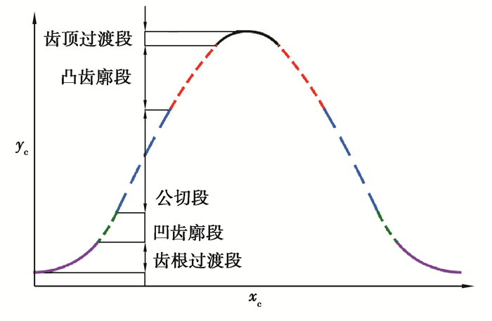
利用运动学法求得的插刀理论齿形如图 3所示。
|
图 3 插刀理论齿形示意图 Fig. 3 Theoretical tooth profile of the slotting cutter |
插刀本质为由砂轮变位磨削出的变厚齿轮。砂轮磨削插刀可视为齿轮与齿条啮合[20],其中插刀相当于齿轮,砂轮相当于齿条。论文根据插刀理论齿形,通过齿廓法线法,建立了砂轮磨削加工数学磨削,推导了砂轮齿廓,最后通过变位磨削求出了不同截面插刀的等效齿形。
2.1 砂轮磨削加工数学模型根据啮合原理可知插刀与砂轮的啮合方程为
| $ \boldsymbol{n}_{\mathrm{c}} \cdot \boldsymbol{v}_{\mathrm{c}}^{\mathrm{sc}}=0, $ | (14) |
式中:nc为插刀上啮合点的齿廓法向量;vcsc为在插刀坐标系中砂轮与插刀啮合点的相对速度。
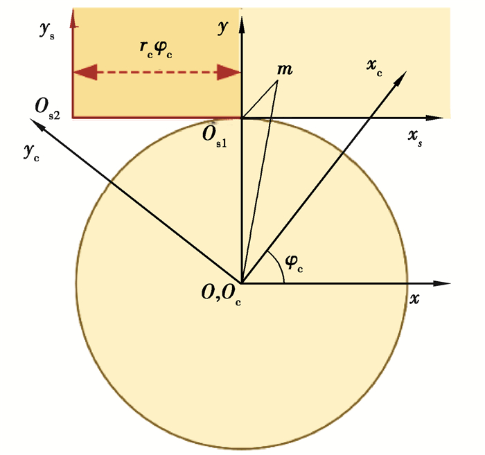
如图 4所示,分别建立与砂轮、插刀固连的坐标系Ss(xsosys)、Sc(xcocyc)以及固定坐标系S(xoy)。
|
图 4 磨削加工坐标系 Fig. 4 Coordinate system of the simulation model of grinding the slotting cutter |
设插刀齿廓上任一点m(xm, ym)处的切线与xc轴的夹角γ为
| $ \tan \gamma=\frac{\mathrm{d} y_{\mathrm{c}}(u)}{\mathrm{d} x_{\mathrm{c}}(u)}。$ | (15) |
插刀转角φc为
| $ \left\{\begin{array}{l} \cos \psi=\frac{x_m \cos \gamma+y_m \sin \gamma}{r_{\mathrm{c}}}, \\ \varphi_{\mathrm{c}}=\frac{\pi}{2}-(\gamma+\psi)。\end{array}\right. $ | (16) |
在坐标系Sc(xcocyc)中,插刀齿面接触点的位矢为
| $ \overrightarrow{r_{r l}}=x_{\mathrm{c}} \overrightarrow{i_2}+y_{\mathrm{c}} \overrightarrow{j_2} \text { 。} $ | (17) |
把啮合线坐标从坐标系Sc(xcocyc)转换到坐标系Ss(xsosys)中,则砂轮齿廓为
| $ \overrightarrow{r_{\mathrm{g}}}=M_{\mathrm{sc}} \cdot \overrightarrow{r_{r l}}, $ | (18) |
其中,从插刀坐标系转到砂轮坐标系的变换矩阵Msc为
| $ \boldsymbol{M}_{\mathrm{sc}}=\left[\begin{array}{ccc} \cos \varphi_{\mathrm{c}} & -\sin \varphi_{\mathrm{c}} & r_{\mathrm{c}} \varphi_{\mathrm{c}} \\ \sin \varphi_{\mathrm{c}} & \cos \varphi_{\mathrm{c}} & -r_{\mathrm{c}} \\ 0 & 0 & 1 \end{array}\right] 。$ | (19) |
砂轮齿廓方程为
| $ \left\{\begin{array}{l} x_{\mathrm{s}}=x_{\mathrm{c}} \cos \varphi_{\mathrm{c}}-y_{\mathrm{c}} \sin \varphi_{\mathrm{c}}-r_{\mathrm{c}} \varphi_{\mathrm{c}}, \\ y_{\mathrm{s}}=x_{\mathrm{c}} \sin \varphi_{\mathrm{c}}+y_{\mathrm{c}} \cos \varphi_{\mathrm{c}}-r_{\mathrm{c}}。\end{array}\right. $ | (20) |
砂轮齿廓如图 5所示。
|
图 5 砂轮齿形 Fig. 5 Tooth profile of the grinding wheel |
由图 5可知,磨削插刀的砂轮齿廓同样由齿顶圆弧段、凸齿廓段、公切段、凹齿廓段以及齿根过渡段组成。
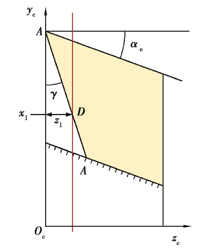
2.2 插刀切削刃数学模型插刀切削刃为空间齿形,以插刀回转轴作为zc轴,将与插刀固连的坐标系扩展为空间坐标系Sc(xcyczc)。插刀切削刃在Sc(ycoczc)内的投影如图 6所示。
|
图 6 插刀切削刃投影 Fig. 6 Projection of the cutting edge of the slotting cutter |
由图可知插刀切削刃上任一点D对应的变位系数为x1,其中zc坐标与变位系数的关系为
| $ x_1 m=z_1 \tan \alpha_{\mathrm{e}}, $ | (21) |
式中,m为插刀模数。
因此插刀前刀面切削刃上各点对应的半径为
| $ r_{21}=r_{\mathrm{c}}-z_1 \tan \alpha_{\mathrm{e}} \text { 。} $ | (22) |
由此插刀切削刃各点求解方程为
| $ \left\{\begin{array}{l} x_{\mathrm{c}}=x_{\mathrm{s}} \cos \varphi_{\mathrm{c}}+y_{\mathrm{s}} \sin \varphi_{\mathrm{c}}+r_{211}, \\ y_{\mathrm{c}}=-x_{\mathrm{s}} \sin \varphi_{\mathrm{c}}+y_{\mathrm{s}} \cos \varphi_{\mathrm{c}}+r_{212}, \\ r_{211}=r_{21}\left(-\varphi_{\mathrm{c}} \cos \varphi_{\mathrm{c}}+\sin \varphi_{\mathrm{c}}\right), \\ r_{212}=r_{21}\left(\cos \varphi_{\mathrm{c}}+\varphi_{\mathrm{c}} \sin \varphi_{\mathrm{c}}\right) 。\end{array}\right. $ | (23) |
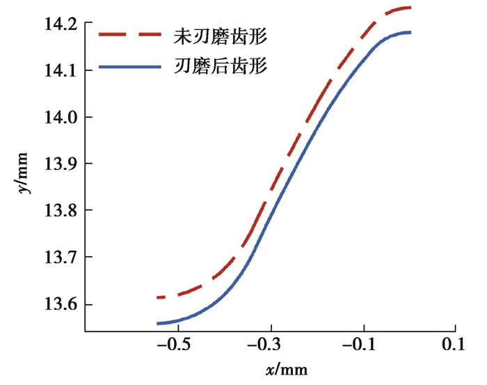
则刃磨后插刀的等效齿形,如图 7所示。
|
图 7 刃磨后插刀齿形 Fig. 7 Tooth profile of the sharpened slotting cutter |
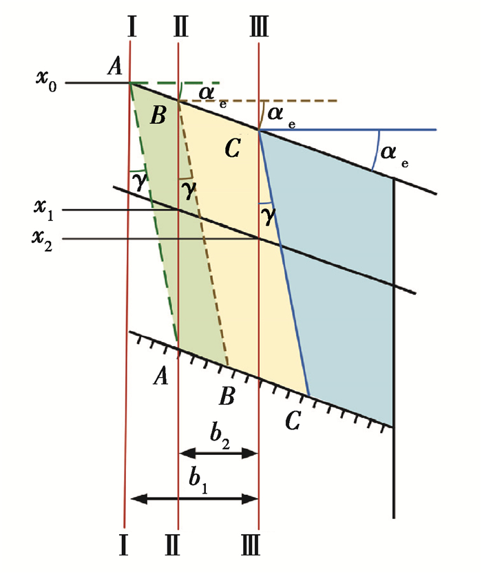
刃磨后,插刀前角不变,外径减小,与刚轮啮合时中心距减小,如图 8所示。刃磨一次后,插刀前刀面由A-A截面变为了B-B截面,插刀基面从Ⅰ截面变为Ⅱ截面,变位系数由x0变为x1。插刀与刚轮啮合时的中心距ec1为
| $ e_{\mathrm{c1}}=e_{\mathrm{c}}+\left(x_1-x_0\right) m, $ | (24) |
|
图 8 刃磨后插刀前刀面 Fig. 8 Rake face of the sharpened slotting cutter |
式中:ec为未刃磨时插刀与刚轮啮合时的中心距;x0为未刃磨时插刀基面内齿形的变位系数;x1为插刀刃磨一次后插刀基面内齿形的变位系数。
由此插刀刃磨后,由坐标系Sr(xroryr)到Sc(xcocyc)的坐标转换矩阵mcr为
| $ \left[\begin{array}{ccc} \cos \varphi & \sin \varphi & -e_{\mathrm{c} 1} \sin \varphi_{\mathrm{c}} \\ -\sin \varphi & \cos \varphi & -e_{\mathrm{cl}} \cos \varphi_{\mathrm{c}} \\ 0 & 0 & 1 \end{array}\right] 。$ | (25) |
设插刀切削刃上任一点D的坐标为(xd1, yd1, zd1),插刀顶点A的坐标为(xa, ya, za),则插刀前刀面切削刃在Sc(ycoczc)内投影直线的数学模型为
| $ \left\{\begin{array}{l} k_{\mathrm{d} 1}=\tan \left(\gamma+\frac{\pi}{2}\right), \\ y=k_{\mathrm{d} 1}\left(z-z_{\mathrm{a}}\right)+y_{\mathrm{a}}, \end{array}\right. $ | (26) |
式中:kd1为切削刃投影直线斜率;γ为插刀顶刃前角。
刃磨后,插刀与刚轮之间的中心距改变,通过刃磨后插削加工数学仿真模型可求出刃磨后插刀顶点A的坐标。
刃磨后插刀纵坐标最大值ymax为
| $ y_{\max }=y_{\mathrm{a}} \text {, } $ | (27) |
刃磨后,插刀的前角与后角不变,插刀上任一点D的y坐标、z坐标与变位系数之间的关系为
| $ \left\{\begin{array}{l} z_{\mathrm{d} 1}=\left(y_{\max }-y_{\mathrm{d} 1}\right) \tan \gamma, \\ x_{\mathrm{d}} m=z_{\mathrm{d} 1} \tan \alpha_{\mathrm{e}}, \end{array}\right. $ | (28) |
式中,xd为D点所在截面插刀齿形的变位系数。
则根据啮合方程与公式(26)(27)与(28),可建立插刀切削刃的数学模型,而后根据切削刃的横纵坐标,可求出不同截面插刀的等效齿形。
3.3 刚轮齿形误差分析按照小模数插刀的行业标准:JB/T 3095—2006。当插刀精度要求为AA级时,如插刀模数为0.1~0.5 mm以内,要求插刀的齿形误差应该不大于3 μm。因此以3 μm刚轮齿形误差为标准评判插刀的有效长度。
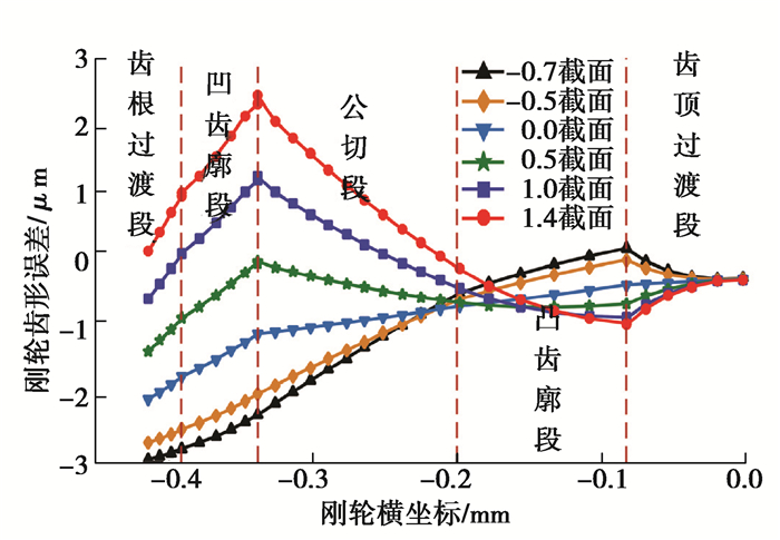
当插刀齿数为55时,以插刀原始截面为基面的插刀为0截面插刀,刃磨后插刀基面距离原始截面β mm的截面为β截面插刀,β为正值时,插刀基面位于原始截面右侧;β为负值时,插刀基面位于原始截面左侧。根据不同截面插刀的等效齿形,通过插削加工数学仿真磨削,可求出不同截面插刀加工出刚轮的实际齿形,通过对比刚轮实际齿形与理论齿形可得到55齿不同截面插刀加工出刚轮的齿形误差如图 9所示。
|
图 9 55齿各截面插刀对应刚轮齿形误差 Fig. 9 Tooth-profile error of the circular spline machined by the different cross-section slotting cutters with 55 teeth |
由图 9可知,55齿插刀加工出的刚轮齿形误差变化趋势随截面变化而变化,0截面插刀加工出刚轮的齿形误差从齿顶过渡段至齿根过渡段逐渐增加至最大。负截面插刀加工出刚轮的齿形误差从齿顶过渡段至齿根过渡段先减小后增加至最大;负截面插刀加工出刚轮的最大齿形误差为负值,位于齿根过渡段,最小齿形误差位于齿顶过渡段与凸齿廓段的交界处;-0.7截面插刀加工出齿形误差为-3 μm的刚轮。正截面插刀加工出刚轮的齿形误差在齿顶过渡段逐渐增加,在凹齿廓段与公切段内先减小后增加,在凹齿廓段与齿根过渡段逐渐减小;正截面插刀加工出刚轮的齿形误差最大值为正值,位于凹齿廓段与公切段的交界处,1.4截面插刀加工出齿形误差为3 μm的刚轮。因此以刚轮齿形误差为3 μm作为标准,插刀有效长度为2.1 mm。
4 双圆弧刚轮插刀有效长度优化 4.1 砂轮齿形优化当插齿刀的顶刃前角γ>0°时,刀具的前刀面为圆锥面,前刀面和齿形表面(双圆弧螺旋面)的交线(切削刃)为空间齿形,由于插齿刀顶刃和侧刃都有后角,插刀切削刃上各点对应的不同端剖面中的齿形相当于不同变位系数齿轮的齿形,因此切削刃在基面中的投影不是插刀的理论齿形[17]。为使插刀在基面的投影齿形为理论齿形,论文将插刀切削刃离散为点,计算切削刃上各点所在端剖面内齿形的变位系数,根据变位系数,通过变位磨削加工数学模型,反求砂轮齿廓。由于顶刃后角的存在,插刀切削刃上任一点D对应的节圆半径为
| $ r_{\mathrm{d} 1}=r_{\mathrm{c}}-z_{\mathrm{d} 1} \tan \alpha_{\mathrm{e}}, $ | (29) |
则从插刀坐标系变换到砂轮坐标系的变换矩阵Msc为
| $ \left[\begin{array}{ccc} \cos \varphi_{\mathrm{c}} & -\sin \varphi_{\mathrm{c}} & r_{\mathrm{d} 1} \varphi_{\mathrm{c}} \\ \sin \varphi_{\mathrm{c}} & \cos \varphi_{\mathrm{c}} & -r_{\mathrm{d} 1} \\ 0 & 0 & 1 \end{array}\right] 。$ | (30) |
优化后砂轮齿廓数学模型为
| $ \left\{\begin{array}{l} x_{\mathrm{s}}=x_{\mathrm{c}} \cos \varphi_{\mathrm{c}}-y_{\mathrm{c}} \sin \varphi_{\mathrm{c}}-r_{\mathrm{d} 1} \varphi_{\mathrm{c}}, \\ y_{\mathrm{s}}=x_{\mathrm{c}} \sin \varphi_{\mathrm{c}}+y_{\mathrm{c}} \cos \varphi_{\mathrm{c}}-r_{\mathrm{d} 1} 。\end{array}\right. $ | (31) |
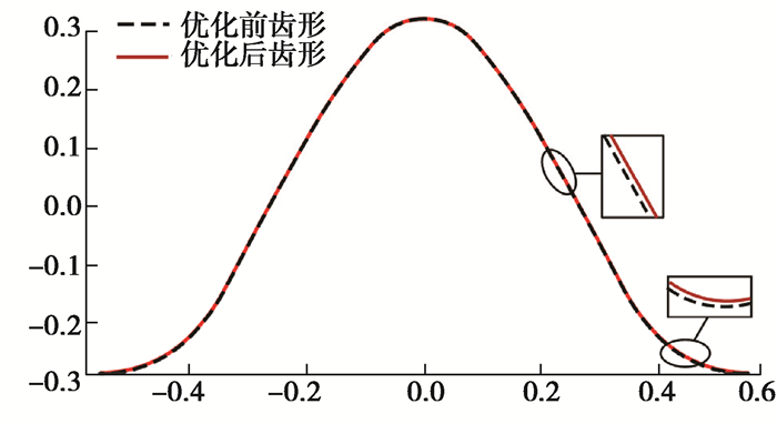
优化后的砂轮齿形如图 10所示。
|
图 10 优化前后的砂轮齿形 Fig. 10 Grinding wheel tooth profile before and after optimization |
由图 10可知,优化后砂轮齿形纵坐标增加,齿形位置上移,在齿根过渡段,变化最大。
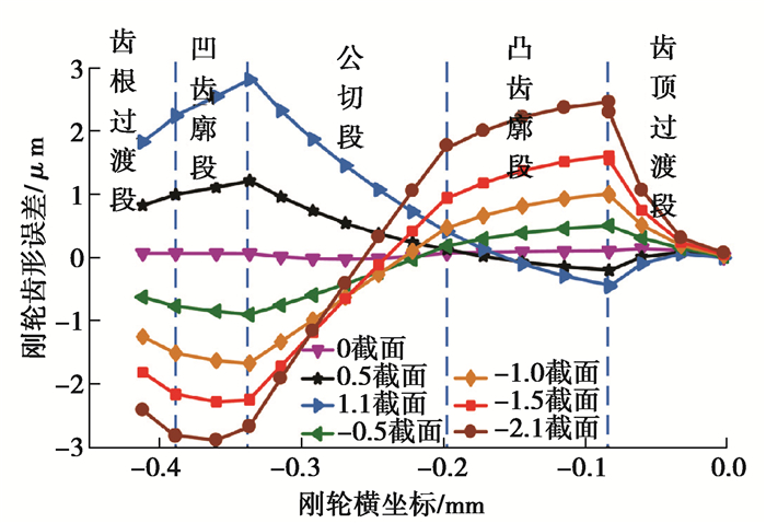
根据砂轮磨削数学模型可求解出优化后不同截面的插刀等效齿形;根据优化后不同截面的插刀等效齿形可求出刚轮齿形。优化后不同截面插刀加工出刚轮的齿形误差如图 11所示。
|
图 11 优化后55齿插刀各截面对应的刚轮齿形误差 Fig. 11 Tooth-profile error of the circular spline machined by the different cross-section slotting cutters with 55 teeth after optimization |
由图 11可知,优化后55齿插刀加工出刚轮的齿形误差变化趋势随截面变化而变化,0截面插刀加工出刚轮的齿形误差最大值为0.14 μm。负截面插刀加工出刚轮的齿形误差在齿顶过渡段逐渐增大,在凸齿廓段逐渐减小,在公切段先减小后增大,在凹齿廓段先增大后减小,在齿根过渡段逐渐减小;负截面插刀加工出刚轮的齿形误差最大值为负值,位于凹齿廓段;-2.1截面插刀加工出了齿形误差为-3 μm的刚轮。正截面插刀加工出刚轮的齿形误差在齿顶过渡段逐渐增加,在凹齿廓段与公切段内先减小后增加,在凹齿廓段与齿根过渡段逐渐减小;正截面插刀加工出刚轮的齿形误差最大值为正值,位于凹齿廓段与公切段的交界处,1.1截面插刀加工出齿形误差为3 μm的刚轮。因此优化后插刀有效长度为3.2 mm。相对未优化时插刀有效长度2.1 mm,延长了1.0 mm,增加了52%的有效长度。
4.2 插刀齿数优化当插刀齿数zc变化时,插刀分度圆半径rc、插刀与刚轮的中心距ec为
| $ \left\{\begin{array}{l} r_{\mathrm{c}}=m z_{\mathrm{c}}, \\ e_{\mathrm{c}}=m \frac{z_{\mathrm{r}}-z_{\mathrm{c}}}{2} 。\end{array}\right. $ | (32) |
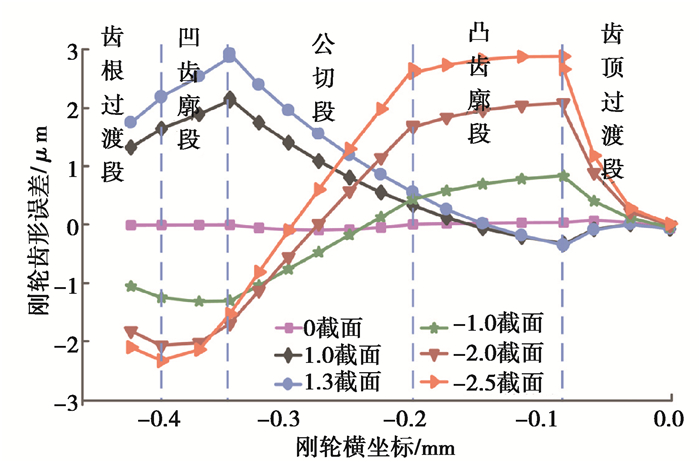
根据前文所述理论,优化后43齿与68齿插刀加工出刚轮的齿形误差,如图 12与图 13所示。
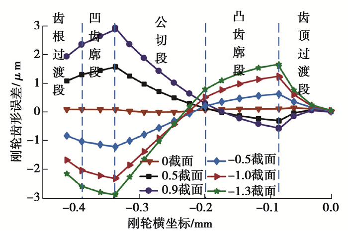
|
图 12 优化后42齿插刀各截面对应的刚轮齿形误差 Fig. 12 Tooth-profile error of the circular spline machined by the different cross-section slotting cutters with 42 teeth after optimization |
|
图 13 优化后68齿插刀各截面对应的刚轮齿形误差 Fig. 13 Tooth-profile error of the circular spline machined by the different cross-section slotting cutters with 68 teeth after optimization |
由图 12可知,优化后42齿插刀加工出刚轮的齿形误差变化趋势随截面变化而变化。0截面插刀加工出刚轮的齿形误差最大值为0.14 μm。负截面插刀加工出刚轮的齿形误差在齿顶过渡段逐渐增大,在凸齿廓段逐渐减小,在公切段先减小后增大,在凹齿廓段与齿根过渡段逐渐减小;负截面插刀加工出刚轮的齿形误差最大值为负值,位于凹齿廓段与公切段的交界处;-1.3截面插刀加工出了齿形误差为-3 μm的刚轮。正截面插刀加工出刚轮的齿形误差在齿顶过渡段逐渐增加,在凹齿廓段内先减小后增加,在公切段逐渐增加,在凹齿廓段与齿根过渡段逐渐减小;正截面插刀加工出刚轮的齿形误差最大值为正值,位于凹齿廓段与公切段的交界处,0.9截面插刀加工出齿形误差为3 μm的刚轮。优化后42齿插刀有效长度为2.2 mm,延长了0.1 mm。
由图 13可知,优化后68齿插刀加工出刚轮的齿形误差变化趋势随截面变化而变化。0截面插刀加工出刚轮的齿形误差最大值为0.14 μm。负截面插刀加工出刚轮的齿形误差在齿顶过渡段增大,在凸齿廓段逐渐减小,在公切段先减小后增大,在凹齿廓段先减少后增大,在齿根过渡段逐渐减小;负截面插刀加工出刚轮的齿形误差最大值为正值,位于凸齿廓段与齿顶过渡段的交界处;-2.5截面插刀加工出了齿形误差为-3 μm的刚轮。优化后正截面插刀加工出刚轮的齿形误差在齿顶过渡段逐渐增加,在凹齿廓段内先减小后增加,在公切段逐渐增加,在凹齿廓段与齿根过渡段逐渐减小;正截面插刀加工出刚轮的齿形误差最大值为正值,位于凹齿廓段与公切段的交界处,优化后1.3截面插刀加工出齿形误差为3 μm的刚轮。因此优化后68齿插刀有效长度为3.8 mm。相对未优化时55齿插刀有效长度2.1 mm,延长了1.7 mm。
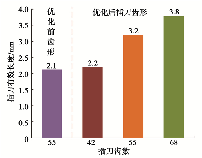
综上,优化前后不同齿数插刀的有效长度如图 14所示。
|
图 14 优化前后不同齿数插刀的有效长度 Fig. 14 Effective length of the slotting cutters with different tooth number before and after optimization |
由图 14可知,优化后42齿、55齿、68齿插刀有效长度分别为2.2、3.2、3.8 mm,因此插刀齿数越大,插刀有效长度越长。优化前55齿插刀有效长度为2.1 mm,其齿数大于42齿插刀,但有效长度小于2.2 mm,因此论文提出的砂轮齿形优化方法有效延长了插刀有效长度。同样增加13齿,插刀有效长度增加的长度并不相同:42齿到55齿,有效长度增加1.1 mm,55齿到68齿,有效长度增加0.6 mm。
5 结论文中建立了基于刚轮齿廓的插削加工数学模型与砂轮磨削数学模型,分析了插刀的有效长度,并通过优化砂轮齿形与插刀齿数延长了插刀的有效长度。主要结论如下:
1) 插刀加工出的刚轮齿形误差变化趋势随截面变化而变化;优化前0截面插刀加工出刚轮的齿形误差为2 μm,优化后0截面插刀加工出刚轮的齿形误差趋于0。
2) 优化后正截面插刀加工出刚轮的齿形误差最大值为正值,位于凹齿廓段与公切段的交界处;负截面插刀加工出刚轮的齿形误差齿数较少时为负值,齿数较大时为正值。
3) 砂轮齿形优化后,随插刀齿数增加,插刀有效长度逐渐增加;优化后68齿插刀有效长度相对于未优化时55齿插刀有效长度延长了1.7 mm,延长了81%。
| [1] |
Popov P K. Preparation for manufacturing of new generation harmonic drive in Russia[J]. Gearing and Transmissions, 1996(1): 33-40. |
| [2] |
Ruderman M, Bertram T, Iwasaki M. Modeling, observation, and control of hysteresis torsion in elastic robot joints[J]. Mechatronics, 2014, 24(5): 407-415. DOI:10.1016/j.mechatronics.2014.02.009 |
| [3] |
辛洪兵. 双圆弧谐波齿轮传动基本齿廓设计[J]. 中国机械工程, 2011, 22(6): 656-662. Xin H B. Design for basic rack of harmonic drive with double-circular-arc tooth profile[J]. China Mechanical Engineering, 2011, 22(6): 656-662. (in Chinese) |
| [4] |
辛洪兵. 研究谐波齿轮传动啮合原理的一种新方法[J]. 中国机械工程, 2002, 13(3): 181-183. Xin H B. A new method for research on engagement principle of harmonic drive[J]. China Mechanical Engineering, 2002, 13(3): 181-183. (in Chinese) |
| [5] |
Chen X X, Liu Y S, Xing J Z, et al. The parametric design of double-circular-arc tooth profile and its influence on the functional backlash of harmonic drive[J]. Mechanism and Machine Theory, 2014, 73: 1-24. DOI:10.1016/j.mechmachtheory.2013.10.003 |
| [6] |
陈晓霞, 牛洪波, 姚云鹏, 等. 渐开线谐波齿轮柔轮最高装配应力分析研究[J]. 华中科技大学学报(自然科学版), 2020, 48(5): 73-79. Chen X X, Niu H B, Yao Y P, et al. Study on analysis of maximum assembly stress of flexspline in involute harmonic drive[J]. Journal of Huazhong University of Science and Technology (Natural Science Edition), 2020, 48(5): 73-79. (in Chinese) |
| [7] |
董惠敏, 董博, 王德伦, 等. 基于瞬心线的谐波传动双圆弧齿形设计方法[J]. 华中科技大学学报(自然科学版), 2020, 48(4): 55-60. Dong H M, Dong B, Wang D L, et al. Double circular arc tooth profile design method of harmonic drives based on centrodes[J]. Journal of Huazhong University of Science and Technology (Natural Science Edition), 2020, 48(4): 55-60. (in Chinese) |
| [8] |
朱飞鸿, 杜雪松, 宋朝省, 等. 考虑柔轮杯体变形的谐波传动空间共轭齿廓设计与分析[J]. 中南大学学报(自然科学版), 2020, 51(9): 2471-2479. Zhu F H, Du X S, Song C S, et al. Design and analysis of space conjugate tooth profile of harmonic drive considering deformation of flexspline cup[J]. Journal of Central South University (Science and Technology), 2020, 51(9): 2471-2479. (in Chinese) |
| [9] |
Li X Z, Song C S, Yang Y, et al. Optimal design of wave generator profile for harmonic gear drive using support function[J]. Mechanism and Machine Theory, 2020, 152: 103941. |
| [10] |
姜歌东, 王爽, 梅雪松, 等. 谐波齿轮传动双圆弧齿形双向共轭设计方法[J]. 西安交通大学学报, 2019, 53(8): 8-14. Jiang G D, Wang S, Mei X S, et al. Bidirectional conjugate design method for double-circular-arc tooth profile of harmonic drives[J]. Journal of Xi'an Jiaotong University, 2019, 53(8): 8-14. (in Chinese) |
| [11] |
Lai H, Wu D. An enhanced DFM model for shaper Cutters[J]. International Journal of Advanced Manufacturing Technology, 2002, 19(7): 482-491. |
| [12] |
Yamazaki H, Yoshida Y, Kiyosawa Y, et al. A study of designing and manufacturing method of pinion cutter for non-involute gear: 4th report, an analysis for profile error of resharpened pinion cutter[J]. The Proceedings of the Symposium on Motion and Power Transmission, 2004, 2004: 334-336. |
| [13] |
Yamazaki H, Yoshida Y, Kiyosawa Y, et al. 801 A study of designing and manufacturing method of pinion cutter for non-involute gear: 5th report, an examination for relief surface with small profile error after re-sharpening[J]. The Proceedings of Conference of Hokuriku-Shinetsu Branch, 2006, 2006(43): 249-250. |
| [14] |
Kawalec A, Wiktor J, Ceglarek D. Comparative analysis of tooth-root strength using ISO and AGMA standards in spur and helical gears with FEM-based verification[J]. Journal of Mechanical Design, 2006, 128(5): 1141-1158. |
| [15] |
Lin S W, Han C S, Tan J B, et al. Mathematical models for manufacturing a novel gear shaper cutter[J]. Journal of Mechanical Science and Technology, 2010, 24(1): 383-390. |
| [16] |
Máté M, Hollanda D. Numerical evaluation of the shaper cutter with cylindrical rake face[J]. Müszaki Tudományos Közlemények, 2020, 12(1): 55-62. |
| [17] |
景艳, 杜雪松, 宋朝省, 等. 双圆弧谐波传动刚轮插齿刀设计与齿形误差分析[J]. 重庆大学学报, 2021, 44(6): 60-72. Jing Y, Du X S, Song C S, et al. Design and tooth profile error analysis of a rigid gear-shaper cutter with double-circular-arc harmonic drive[J]. Journal of Chongqing University, 2021, 44(6): 60-72. (in Chinese) |
| [18] |
李佳, 李晓群, 王鹏, 等. 无理论刃形误差直齿插齿刀设计[J]. 中国机械工程, 2015, 26(12): 1563-1568. Li J, Li X Q, Wang P, et al. Design of straight teeth gear shaping cutter without theoretical cutting edge profile errors[J]. China Mechanical Engineering, 2015, 26(12): 1563-1568. (in Chinese) |
| [19] |
王仕璞, 宋朝省, 朱才朝, 等. 正前角双圆弧谐波传动柔轮滚刀设计与齿形误差分析[J]. 西安交通大学学报, 2021, 55(1): 127-135. Wang S P, Song C S, Zhu C C, et al. Design and tooth profile error analysis of double-circular-arc harmonic flexspline hob with positive rake angle[J]. Journal of Xi'an Jiaotong University, 2021, 55(1): 127-135. (in Chinese) |
| [20] |
王庆男. 高精度插齿刀磨齿机减振与插齿实验研究[D]. 大连: 大连理工大学, 2010: 15-17. Wang Q N. Experimental research on vibration-damping of high-precision gear-shaper-cutter grinder and gear shaping[D]. Dalian: Dalian University of Technology, 2010: 15-17. (in Chinese) |
 2023, Vol. 46


