1a. 重庆大学 机械传动国家重点实验室, 重庆 400044;
1b. 重庆大学 机械工程学院, 重庆 400044;
2. 中国船舶重工集团公司 第七一一研究所, 上海 200090
收稿日期: 2013-08-03
基金项目: 国家“973”资助项目(2014CB049403);国家自然科学基金资助项目(51175525);重庆大学机械传动国家重点实验室自主研究基金资助项目(0301002109137)
Analysis on study of spatial curve model of steel wire isolator with circle elastic element
1a. The State Key Laboratory of Mechanical Transmission, Chongqing University, Chongqing 400044, China;
1b. College of Mechanical Engineering, Chongqing University, Chongqing 400044, China;
2. The No. 711 Research Institute of China Shipbuilding Industry Corp, Shanghai 200090, China
钢丝绳隔振器是美国在70年代末研制成功的一种非线性隔振器材,由于钢丝绳隔振器有不同于其他非线性材料的优异特性,如固有频率低,对低频高频干扰都有良好的隔振性能,在应对冲击时又有良好的软化特性,工作温度范围大,耐腐蚀等优点,使得其运用非常广泛,越来越多的被应用于航空航天如导弹、卫星运载、导航与发射系统的安全防护,机载、车载、舰载等电子、机械设备与仪器仪表的隔振缓冲中,但是针对结构参数对其静动态设计影响的理论和方法研究滞后[1]。
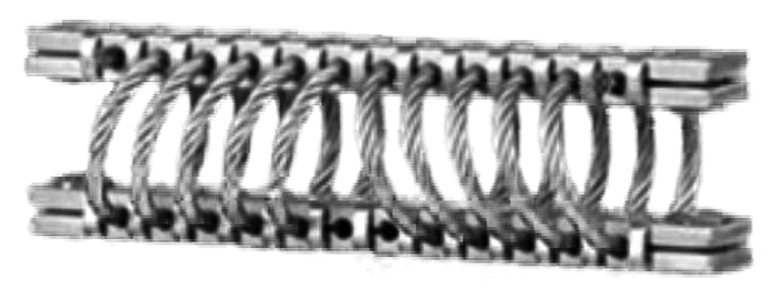
钢丝绳隔振器类型众多,总的分类有T型、G型、Q型3种结构[2],图 1所示为T型。
T型结构的钢丝绳隔振器主要是由一根钢丝绳缠绕固定在夹板之间,此种结构的钢丝绳隔振器生产流程复杂,加工难度高,安装不便,不易拆卸,损坏后不能方便及时的重新装夹使用。此种隔振器性能控制参数主要由钢丝绳规格、钢丝绳缠绕的圈数、缠绕螺旋倾斜角决定,其结构参数对刚度、阻尼特性的影响有待深入研究。
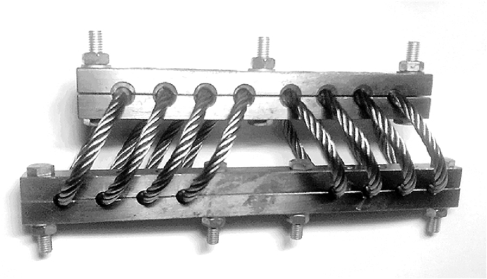
针对上述问题,设计了如图 2所示的新型环型单元钢丝绳隔振器,其中的钢丝绳绳圈采取简单夹具和铜焊方法连接2端,如图 3所示。这种结构的钢丝绳隔振器有以下优点:1)装夹方便,不需要专用工装;2)环型钢丝绳弹性元件可以由不同规格的钢丝绳做成,相同大小的绳圈可以组合装夹使用;3)使用寿命长,当某个绳圈损坏失效后可以方便及时的更换;4)简化了研究对象,由于隔振器是多个钢丝绳绳圈并联使用,因此当确定了结构参数对单个钢丝绳绳圈性能的影响就可以推导出结构参数对整个钢丝绳隔振器的刚度等特性的影响。另外,对于确定规格钢丝绳、确定大小的钢丝绳绳圈,在其受到振动载荷作用时,它的内部在一定条件下发生摩擦、滑移的性能相比较隔振器整体而言要容易确定,这对于研究钢丝绳绳圈结构参数对钢丝绳隔振器的刚度、阻尼等动态特性有重要作用。
对于提出的新型隔振器的钢丝绳绳圈,在研究其受到振动载荷作用时,钢丝绳绳圈几何模型是研究其结构参数对钢丝绳隔振器的刚度、阻尼等特性影响的基础,对其仿真研究具有重要意义,故拟对此进行研究。
1 钢丝绳绳圈空间几何的建模
随着计算机及仿真软件的发展,特别是软件加入了对材料非线性、几何非线性等非线性因素的考虑,使其仿真研究结果对现实应用有很好的指导作用,利用计算机对钢丝绳进行仿真应用的研究方法也越来越多的被研究者所使用,如王桂兰[3-6]、孙建芳[7-8]对钢丝绳加工过程中的残余应力及摩擦进行的深入研究,马军[9-11]对钢丝绳股内钢丝计算机建模,及钢丝内部应力应变的分析。
对于钢丝绳模型的建立,目前主要有以下几种方法:1)直接以圆柱体代替钢丝绳,如闫辉[12]等在使用ANSYS进行模拟时,将钢丝绳看成悬臂梁结构整体建模分析,此种方法忽略了丝与丝之间的摩擦,不能充分反应钢丝绳的特性。2)模型中芯绳中心线法平面截取钢丝绳后,所得截面形状为圆形,如马军[9-11]、Usabiaga[13]等对钢丝绳进行仿真研究时均采用的此种模型,这种钢丝绳截面是在未捻制状态下的截面,此种模型不能真实反映钢丝绳内部结构。3)模型中芯绳中心线法平面截取钢丝绳后,侧丝截面为椭圆,此种模型考虑了钢丝绳的扭转效应,对于直径相似、捻角较大的钢丝绳结构具有很好的近似度,但一般研究只针对芯绳结构,对侧绳结构没有进行过深入的探讨[14]。
对于提出的新型钢丝绳隔振器,其刚度K、阻尼C是绳圈直径D、绳圈个数N、绳圈倾斜角度γ、钢丝绳直径d、股绳数a、钢丝数b、钢丝半径R、以及钢丝绳捻角β等结构参数的函数,对钢丝绳绳圈进行精确建模是仿真分析绳环内部摩擦、滑移的基础。鉴于以上原因,对钢丝绳绳圈空间曲线模型进行研究。
1.1 钢丝绳绳圈空间几何模型建立的基本原理
钢丝绳生产时,芯绳与股绳必须相切,即芯绳要支撑股绳,而股绳之间可以有空隙,若相切将使钢丝绳有更大的承载能力。在仿真计算中,若这些初始的结构参数条件未仔细考虑,计算结果将产生很大偏差。目前,被广泛接受的钢丝绳建模假设是钢丝中心线任意一点主法向量与副法向量所在平面去截钢丝,钢丝截面为圆,基于此假设建立空间钢丝绳中心线模型。
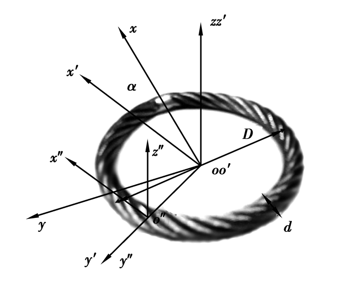
如图 3所示,钢丝绳为7×7结构,其中心线有4种:芯绳芯丝中心线L00;芯绳侧丝中心线L0i;侧绳芯丝中心线Li0;侧绳侧丝中心线Lij。R00表示芯绳芯丝半径;R0j表示芯绳侧丝半径;Ri0表示侧绳芯丝半径;Rij表示侧绳侧丝半径(i,j表示侧绳或侧丝数目,i∈[1, 6];j∈[1, 6];i,j∈N)。
建立坐标系如图 3所示,设oxyz为初始坐标系,其原点o与钢丝绳绳环中心即芯绳芯丝中心线圆心重合,o′x′y′z′为坐标系oxyz绕oz轴逆时针转过α角度后的动坐标系,o″x″y″z″为动坐标系o′x′y′z′沿o′y′轴正向移动$\frac{D}{2} $转换得到,由图 3易知芯绳芯丝中心线在坐标系oxyz下的方程
|
$
{\mathit{\boldsymbol{L}}_{00}} = \left[ \begin{array}{l}
D/2 \times \cos \alpha \\
D/2 \times \sin \alpha \\
0
\end{array} \right],\alpha \in \left[ {0,2{\rm{ \mathit{ π} }}} \right]。$
|
(1) |
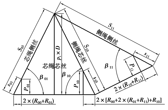
将钢丝绳绳圈假想成未缠绕前的直钢丝绳,则其展开关系如图 4所示,其中6根芯绳侧丝、6根侧绳芯丝以及每根股绳中的6根侧绳侧丝之间的相位角均为60°,得到6根中任意一根的空间曲线方程都可以推导出其他5根中心线的空间曲线方程,因此只研究L00、L01、L10、L11。由几何关系易知芯绳芯丝的长度为π×D,当各侧丝对应其芯丝的捻角分别为β01、β10、β11时,其对应的捻距分别为P01、P10、P11,单位捻距内侧丝长度分别为s01、s10、s11,整环展开后,侧丝总长度分别为S01、S10、S11,钢丝绳各项参数如表 1所示。
表 1(Table 1)

表 1 钢丝绳各项参数如下表所示
| mm |
| 参数 |
R00 |
R01 |
R10 |
R11 |
d |
D |
α |
| 取值 |
0.4 |
0.3 |
0.35 |
0.2 |
5 |
50 |
2π |
| 参数 |
β01 |
β10 |
β11 |
n01 |
n10 |
n11 |
|
| 取值 |
70° |
86.2° |
80° |
20 |
10 |
25 |
|
|
表 1 钢丝绳各项参数如下表所示
|
1.2 典型钢丝中心曲线空间几何模型建立
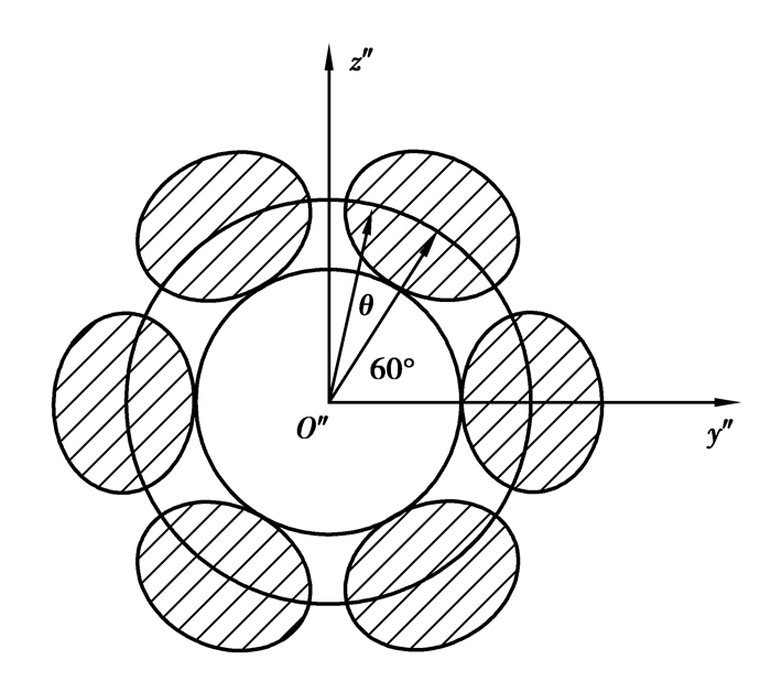
由图 3知o″x″轴为芯绳中心线的切线,所以芯绳芯丝截面是一个圆(见图 5),芯绳芯丝支撑外层6根芯绳侧丝,建立坐标系如图 5所示,选与o″y″成60°的芯绳侧丝L01进行分析研究。
在o″x″y″z″坐标系下,L01的方程为
|
$
{{{\mathit{\boldsymbol{L''}}}_{01}} = \left[ {\begin{array}{*{20}{c}}
0\\
{\left( {{R_{00}} + {R_{01}}} \right) \times \cos \left( {{{60}^ \circ } + {\theta _{01}}} \right)}\\
{\left( {{R_{00}} + {R_{01}}} \right) \times \sin \left( {{{60}^ \circ } + {\theta _{01}}} \right)}\\
1
\end{array}} \right],}
$
|
|
$
{{\theta _{01}} \in \left[ {0,{n_{01}} \times \alpha } \right];{n_{01}} = \frac{{{S_{01}}}}{{{s_{01}}}};\sin {\beta _{01}} = \frac{{{\rm{ \mathit{ π} }} \times D}}{{{S_{01}}}} = \frac{{{P_{01}}}}{{{s_{01}}}};}
$
|
式中的θ01是α的函数,对于同一根芯绳侧丝,在不同的α角度截图钢丝绳绳圈时,θ01值是不同的,在本文中,α=0时截取的截面如图 3所示,建立关系式θ01=n01×α。当取α的初值为0时,θ01的初值也为0,这样,当α=2π角度,即缠绕一圈时,θ01缠绕了${n_{01}} = \frac{{{S_{01}}}}{{{s_{01}}}} $圈。
将此方程转化成L01在坐标系oxyz下的坐标:由上述坐标系建立过程推知,若要将o″x″y″z″还原到oxyz,首先要将o″x″y″z″坐标原点o″平移到o′点,然后顺时针转动,使得o″x″轴与ox轴重合,由空间坐标转换理论易知平移矩阵T,旋转矩阵RT分别为
|
$
\mathit{\boldsymbol{T}} = \left[ {\begin{array}{*{20}{c}}
0&0&0&0\\
0&0&0&0\\
0&0&0&0\\
0&{ - D/2}&0&1
\end{array}} \right],
$
|
|
$
\mathit{\boldsymbol{RT}} = \left[ {\begin{array}{*{20}{c}}
{\cos \alpha }&{\sin \alpha }&0&0\\
{ - \sin \alpha }&{\cos \alpha }&0&0\\
0&0&0&0\\
0&0&0&1
\end{array}} \right]。$
|
由上述推导知L″01=L01×RT×T,所以L01=L″01×T-1×RT-1。
即L01在坐标系oxyz下的方程为
|
$
{\mathit{\boldsymbol{L}}_{01}} = \left[ {\begin{array}{*{20}{c}}
{\left( {\left( {{R_{00}} + {R_{01}}} \right) \times \cos \left( {{{60}^ \circ } + {\theta _{01}}} \right) + D/2} \right) \times \sin \alpha }\\
{\left( {\left( {{R_{00}} + {R_{01}}} \right) \times \cos \left( {{{60}^ \circ } + {\theta _{01}}} \right) + D/2} \right) \times \cos \alpha }\\
{\left( {{R_{00}} + {R_{01}}} \right) \times \sin \left( {{{60}^ \circ } + {\theta _{01}}} \right)}\\
1
\end{array}} \right],
$
|
(2) |
|
$
{\theta _{01}} \in \left[ {0,{n_{01}} \times \alpha } \right];{n_{01}} = \frac{{{S_{01}}}}{{{s_{01}}}};\sin {\beta _{01}} = \frac{{{\rm{ \mathit{ π} }} \times D}}{{{S_{01}}}} = \frac{{{P_{01}}}}{{{s_{01}}}};
$
|
侧绳芯丝的推导过程与芯绳侧丝类似,不同是侧绳芯丝L10在坐标系o″x″y″z″下的分布半径为R=R00+2×R01+2×R11+R10,转动过程中角度的变化θ10=n10×α。L10在坐标系o″x″y″z″下的方程为
|
$
{{\mathit{\boldsymbol{L''}}}_{01}} = \left[ {\begin{array}{*{20}{c}}
0\\
{\left( {{R_{00}} + 2 \times {R_{01}} + 2 \times {R_{11}} + {R_{10}}} \right) \times }\\
{\cos \left( {{{60}^ \circ } + {\theta _{10}}} \right)}\\
{\left( {{R_{00}} + 2 \times {R_{01}} + 2 \times {R_{11}} + {R_{10}}} \right) \times }\\
{\sin \left( {{{60}^ \circ } + {\theta _{10}}} \right)}\\
1
\end{array}} \right],
$
|
|
$
{\theta _{10}} \in \left[ {0,{n_{10}} \times \alpha } \right];{n_{10}} = \frac{{{S_{10}}}}{{{s_{10}}}};\sin {\beta _{10}} = \frac{{{\rm{ \mathit{ π} }} \times D}}{{{S_{10}}}} = \frac{{{P_{10}}}}{{{s_{10}}}};
$
|
同式(2)推导,则L10在坐标系oxyz下的方程为
|
$
\begin{array}{*{20}{c}}
{{\mathit{\boldsymbol{L}}_{10}} = \left[ {\begin{array}{*{20}{c}}
{\left( {R \times \cos \left( {{{60}^ \circ } + {\theta _{10}}} \right) + D/2} \right) \times \sin \alpha }\\
{\left( {R \times \cos \left( {{{60}^ \circ } + {\theta _{10}}} \right) + D/2} \right) \times \cos \alpha ,}\\
{R \times \sin \left( {{{60}^ \circ } + {\theta _{10}}} \right)}\\
1
\end{array}} \right],}\\
{R = {R_{00}} + 2 \times {R_{01}} + 2 \times {R_{11}} + {R_{10}},}\\
{{\theta _{10}} \in \left[ {0,{n_{10}} \times \alpha } \right];{n_{10}} = \frac{{{S_{10}}}}{{{s_{10}}}};\sin {\beta _{10}} = \frac{{{\rm{ \mathit{ π} }} \times D}}{{{S_{10}}}} = \frac{{{P_{10}}}}{{{s_{10}}}}。}
\end{array}
$
|
(3) |
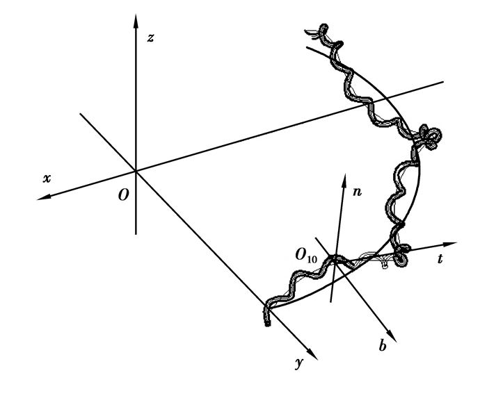
侧绳侧丝的中心线的坐标变换比较复杂,当把o″x″y″z″简单平移转换到其中心线上时,o″x″并不是其中心线曲线的切线。为了解决这个问题,在侧绳芯丝上建立Frenet坐标系(见图 6)。
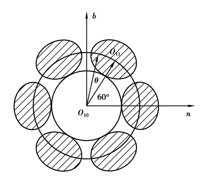
在Frenet坐标系下,侧绳芯丝的截面为圆,此时侧绳截面如图 7所示,O11为此时侧绳侧丝中心线与侧绳芯丝中心线上O10点处法平面的交点。
由上图几何关系知
|
$
{\mathit{\boldsymbol{O}}_{10}}{\mathit{\boldsymbol{O}}_{11}} = \left( {{R_{10}} + {R_{11}}} \right) \times \cos \left( {{{60}^ \circ } + {\theta _{11}}} \right) \cdot \mathit{\boldsymbol{n}} + \left( {{R_{10}} + {R_{11}}} \right) \times \sin \left( {{{60}^ \circ } + {\theta _{11}}} \right) \cdot \mathit{\boldsymbol{b}}。$
|
(4) |
将式(3)中L10写成以α为变量的向量形式
|
$
{\mathit{\boldsymbol{O}}{\mathit{\boldsymbol{O}}_{11}} = \left[ {\begin{array}{*{20}{c}}
{\left( {R \times \cos \left( {{{60}^ \circ } + {n_{10}} \times \alpha } \right) + D/2} \right) \times \sin \left( \alpha \right)}\\
{\left( {R \times \cos \left( {{{60}^ \circ } + {n_{10}} \times \alpha } \right) + D/2} \right) \times \cos \left( \alpha \right)}\\
{R \times \sin \left( {{{60}^ \circ } + {n_{10}} \times \alpha } \right)}
\end{array}} \right],}
$
|
(5) |
|
$
{R = {R_{00}} + 2 \times {R_{01}} + 2 \times {R_{11}} + {R_{10}}。}
$
|
由Frenet坐标系定义知侧绳芯丝中心线上任意一点的切向量t、主法向量n、副法向量b的表达式分别为
|
$
\mathit{\boldsymbol{t}} = \left[ \begin{array}{l}
\frac{{ - 9R \times \cos \left( {9\alpha + {{60}^ \circ }} \right) + 11R \times \cos \left( {11\alpha + {{60}^ \circ }} \right) + D \times \cos \alpha }}{{\sqrt {402{R^2} - 2{R^2} \times \sin \left( {20\alpha + {{30}^ \circ }} \right) + 4D \times R \times \cos \left( {10\alpha + {{60}^ \circ }} \right) + {D^2}} }}\\
\frac{{ - 9R \times \sin \left( {9\alpha + {{60}^ \circ }} \right) - 11R \times \sin \left( {11\alpha + {{60}^ \circ }} \right) - D \times \sin \alpha }}{{\sqrt {402{R^2} - 2{R^2} \times \sin \left( {20\alpha + {{30}^ \circ }} \right) + 4D \times R \times \cos \left( {10\alpha + {{60}^ \circ }} \right) + {D^2}} }}\\
\frac{{20R \times \cos \left( {10\alpha + {{60}^ \circ }} \right)}}{{\sqrt {402{R^2} - 2{R^2} \times \sin \left( {20\alpha + {{30}^ \circ }} \right) + 4D \times R \times \cos \left( {10\alpha + {{60}^ \circ }} \right) + {D^2}} }}
\end{array} \right],
$
|
|
$
R = {R_{00}} + 2 \times {R_{01}} + 2 \times {R_{11}} + {R_{10}}
$
|
|
$
\mathit{\boldsymbol{n}} = \left[ \begin{array}{l}
\frac{{ - 121R \times \sin \left( {11\alpha + {{60}^ \circ }} \right) + 81R \times \sin \left( {9\alpha + {{60}^ \circ }} \right) - D \times \sin \alpha }}{{\sqrt {41\;202{R^2} + 389R \times \sin \left( {20\alpha + {{30}^ \circ }} \right) + 404D \times R \times \cos \left( {10\alpha + {{60}^ \circ }} \right) + {D^2}} }}\\
\frac{{ - 121R \times \cos \left( {11\alpha + {{60}^ \circ }} \right) - 81R \times \cos \left( {9\alpha + {{60}^ \circ }} \right) - D \times \cos \alpha }}{{\sqrt {41\;202{R^2} + 389{R^2} \times \sin \left( {20\alpha + {{30}^ \circ }} \right) + 404D \times R \times \cos \left( {10\alpha + {{60}^ \circ }} \right) + {D^2}} }}\\
\frac{{ - 200R \times \sin \left( {10\alpha + {{60}^ \circ }} \right)}}{{\sqrt {41\;202{R^2} + 389{R^2} \times \sin \left( {20\alpha + {{30}^ \circ }} \right) + 404D \times R \times \cos \left( {10\alpha + {{60}^ \circ }} \right) + {D^2}} }}
\end{array} \right],
$
|
|
$
R = {R_{00}} + 2 \times {R_{01}} + 2 \times {R_{11}} + {R_{10}}
$
|
|
$
\mathit{\boldsymbol{b}} = \left[ {\begin{array}{*{20}{c}}
{{j_1} - \frac{{90 \times D \times R \times \cos (11 \alpha+60^ \circ) }}{{\sqrt {k \times l} }}}\\
{{j_2} + \frac{{110 \times D \times R\sin \left( {9\alpha + {{60}^ \circ }} \right)}}{{\sqrt {k \times l} }}}\\
{ - 2\;468.625 - 606.375\sin \left( {20\alpha + {{30}^ \circ }} \right) - \frac{{8\;925\cos \left( {10\alpha + {{60}^ \circ }} \right)}}{{\sqrt {k \times l} }}}
\end{array}} \right],
$
|
|
$
\begin{array}{*{20}{c}}
{{j_1} = 4\;020{R^2} \times \cos \alpha - 110{R^2}\sin \left( {21\alpha + {{30}^ \circ }} \right) + }\\
{90{R^2}\sin \left( {19\alpha + {{30}^ \circ }} \right) + 110 \times D \times R\cos \left( {9\alpha + {{60}^ \circ }} \right);}
\end{array}
$
|
|
$
\begin{array}{*{20}{c}}
{{j_2} = - 4\;020{R^2}\sin \alpha - 110{R^2}\cos \left( {21\alpha + {{30}^ \circ }} \right) - }\\
{90{R^2}\cos \left( {19\alpha + {{30}^ \circ }} \right) + 90 \times D \times R \times \cos \left( {11\alpha + {{60}^ \circ }} \right);}
\end{array}
$
|
|
$
k = 402{R^2} + {D^2} - 2{R^2} \times \sin \left( {20\alpha + {{30}^ \circ }} \right) + 4D \times R \times \cos \left( {10\alpha + {{60}^ \circ }} \right);
$
|
|
$
l = 4\;1202{R^2} + {D^2} + 398{R^2}\sin \left( {20\alpha + {{30}^ \circ }} \right) + 404 \times D \times R \times \cos \left( {10\alpha + {{60}^ \circ }} \right);
$
|
|
$
\mathit{\boldsymbol{R}} = {\mathit{\boldsymbol{R}}_{00}} + 2 \times {\mathit{\boldsymbol{R}}_{01}} + 2 \times {\mathit{\boldsymbol{R}}_{11}} + {\mathit{\boldsymbol{R}}_{10}}。$
|
侧绳侧丝的中心线的向量表示为OO11,所以
|
$
\mathit{\boldsymbol{O}}{\mathit{\boldsymbol{O}}_{11}} = \mathit{\boldsymbol{O}}{\mathit{\boldsymbol{O}}_{10}} + {\mathit{\boldsymbol{O}}_{10}}{\mathit{\boldsymbol{O}}_{11}}。$
|
(6) |
2 钢丝绳绳圈数学模型的软件实现
根据上述结构参数以及方程(1)~(6),利用Matlab软件可以得到其空间曲线方程
|
$
{\mathit{\boldsymbol{L}}_{00}} = \left[ {\begin{array}{*{20}{c}}
{25 \times \sin \alpha }\\
{25 \times \cos \alpha }\\
0
\end{array}} \right];
$
|
|
$
{\mathit{\boldsymbol{L}}_{01}} = \left[ {\begin{array}{*{20}{c}}
{\left( {0.7\cos \left( {{{60}^ \circ } + 20\alpha } \right) + 25} \right) \times \sin \alpha }\\
{\left( {0.7\cos \left( {{{60}^ \circ } + 20\alpha } \right) + 25} \right) \times \cos \alpha }\\
{0.7\sin \left( {{{60}^ \circ } + 20\alpha } \right)}
\end{array}} \right];
$
|
|
$
{\mathit{\boldsymbol{L}}_{10}} = \left[ {\begin{array}{*{20}{c}}
{\left( {1.75\cos \left( {{{60}^ \circ } + 10\alpha } \right) + 25} \right) \times \sin \alpha }\\
{\left( {1.75\cos \left( {{{60}^ \circ } + 10\alpha } \right) + 25} \right) \times \cos \alpha }\\
{1.75\sin \left( {{{60}^ \circ } + 10\alpha } \right)}
\end{array}} \right];
$
|
|
$
{\mathit{\boldsymbol{L}}_{11}} = \left[ {\begin{array}{*{20}{c}}
{\left( {0.7\cos \left( {{{60}^ \circ } + 10\alpha } \right) + 25} \right) \times \sin \alpha + \frac{{{a_1}}}{{\sqrt {{a_2}} }} + 0.55\sin \left( {25\alpha } \right)\sqrt {{a_3}} }\\
{\left( {0.7\cos \left( {{{60}^ \circ } + 10\alpha } \right) + 25} \right) \times \cos \alpha + \frac{{{a_4}}}{{\sqrt {{a_5}} }} + 0.55\sin \left( {25\alpha } \right)\sqrt {{a_6}} }\\
{0.7\sin \left( {{{60}^ \circ } + 10\alpha } \right) + \frac{{{a_7}}}{{\sqrt {{a_8}} }} - \frac{{770\sin \left( {25\alpha } \right)\sin \left( {10\alpha + 60} \right)}}{{\sqrt {{a_9}} }}}
\end{array}} \right]。$
|
|
$
\begin{array}{*{20}{c}}
{{a_1} = 0.55\cos \left( {25\alpha } \right)\left( {196\;980\cos \alpha - 5\;390\sin \left( {21\alpha + 30} \right) + } \right.}\\
{\left. {4\;410\sin \left( {19\alpha + 30} \right) + 154\;000\cos \left( {9\alpha + 60} \right) - 126\;000\cos \left( {11\alpha + 60} \right)} \right);}
\end{array}
$
|
|
$
\begin{array}{*{20}{c}}
{{a_2} = \left( {59\;698 - 98\sin \left( {20\alpha + 30} \right) + 5\;600\cos \left( {10\alpha + 60} \right)} \right) \times }\\
{\left( {2\;058\;898 + 19\;502\sin \left( {20\alpha + 30} \right) + 565\;600\cos \left( {10\alpha + 60} \right)} \right);}
\end{array}
$
|
|
$
{a_3} = \frac{{ - 847\sin \left( {11\alpha + 60} \right) + 567\sin \left( {9\alpha + 60} \right) - 200\sin \alpha }}{{2\;058\;898 + 19\;502\sin \left( {20\alpha + 30} \right) + 565\;600\cos \left( {10\alpha + 60} \right)}};
$
|
|
$
\begin{array}{*{20}{c}}
{{a_4} = 0.55\cos \left( {25\alpha } \right)\left( { - 196\;980\sin \alpha - 5\;390\cos \left( {21\alpha + 30} \right) - } \right.}\\
{\left. {4\;410\cos \left( {19\alpha + 30} \right) + 154\;000\sin \left( {9\alpha + 60} \right) + 126\;000\sin \left( {11\alpha + 60} \right)} \right);}
\end{array}
$
|
|
$
\begin{array}{*{20}{c}}
{{a_5} = \left( {59\;698 - 98\sin \left( {20\alpha + 30} \right) + 5\;600\cos \left( {10\alpha + 60} \right)} \right) \times }\\
{\left( {2\;058\;898 + 19\;502\sin \left( {20\alpha + 30} \right) + 565\;600\cos \left( {10\alpha + 60} \right)} \right);}
\end{array}
$
|
|
$
{a_6} = \frac{{ - 567\cos \left( {9\alpha + 60} \right) - 847\cos \left( {11\alpha + 60} \right) - 200\cos \alpha }}{{2\;058\;898 + 19\;502\sin \left( {20\alpha + 30} \right) + 565\;600\cos \left( {10\alpha + 60} \right)}};
$
|
|
$
{a_7} = 0.55\cos \left( {25\alpha } \right)\left( { - 69\;498 - 9\;720\sin \left( {20\alpha + 30} \right) - 285\;600\cos \left( {10\alpha + 60} \right)} \right.;
$
|
|
$
\begin{array}{*{20}{c}}
{{a_8} = \left( {59\;698 - 98\sin \left( {20\alpha + 30} \right) + 5\;600\cos \left( {10\alpha + 60} \right)} \right) \times }\\
{\left( {2\;058\;898 + 19\;502\sin \left( {20\alpha + 30} \right) + 565\;600\cos \left( {10\alpha + 60} \right)} \right);}
\end{array}
$
|
|
$
{a_9} = \frac{{ - 567\cos \left( {9\alpha + 60} \right) - 847\cos \left( {11\alpha + 60} \right) - 200\cos \alpha }}{{2\;058\;898 + 19\;502\sin \left( {20\alpha + 30} \right) + 565\;600\cos \left( {10\alpha + 60} \right)}}。$
|
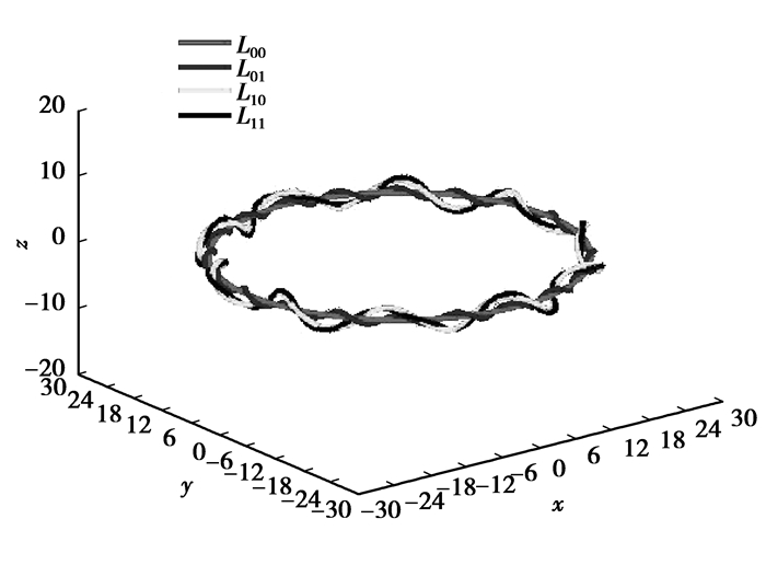
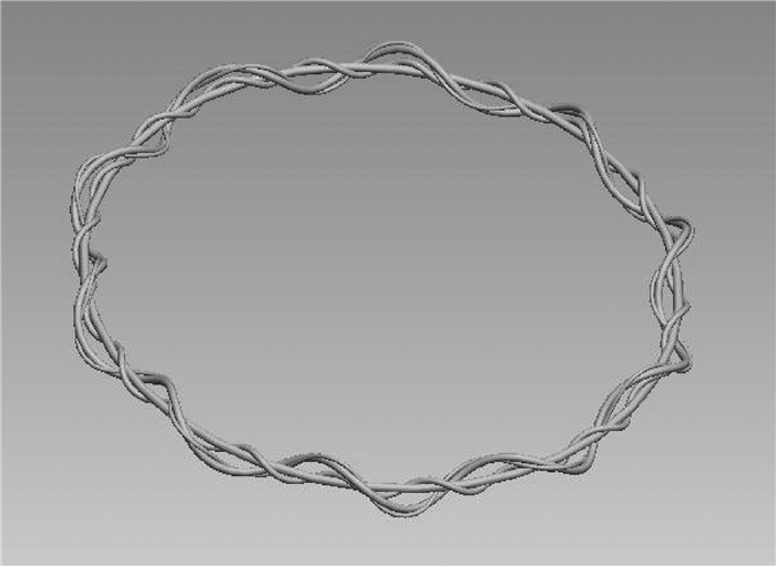
绘制出钢丝绳中心线曲线,其效果图如图 8所示。
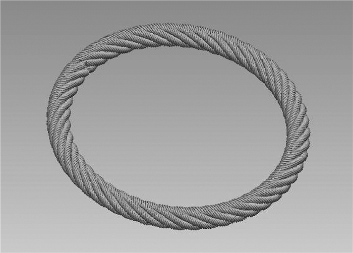
将得到的曲线导入到Pro/E中,得到三维实体模型,如图 9所示。
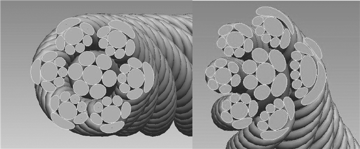
为了方便观察各丝之间的空间相对位置,对钢丝绳绳圈重新进行了空间建模(见图 10),减小侧绳侧丝与芯丝法平面的夹角,建立截面如图 11所示,图中所示截面为芯绳芯丝中心线任意一点法平面截面图和侧绳芯丝中心线任意一点法平面截面图,由图可知若截面为芯绳中心线上任意一点的法平面,则芯丝截面为圆。可以观察到钢丝绳截面是比较复杂的,不能简单的采用圆形或者椭圆截面进行模拟。
3 结论
1) 提出并设计了由多个独立钢丝绳绳圈作为弹性阻尼元件的新型钢丝绳隔振器,其结构规范,便于制造,在实用过程中可方便安装,可以组合使用,为今后设计刚度和阻尼特性可控的新型隔振器创造了条件。
2) 利用空间坐标转换理论推导并提出了钢丝绳绳圈中钢丝绳各丝中心线曲线数学模型,由此通过MATLAB建立了各丝中心线曲线,并导入Pro/E得到了钢丝绳绳圈实体模型,实现了对钢丝绳隔振器绳圈的三维建模。
3) 在钢丝绳绳圈的空间曲线模型建立过程中发现:由研究得到的钢丝绳绳圈实体模型中的芯绳中心线上任意一点被其法平面所截截面不是一般研究文献中所假设的圆形或者椭圆,而是不规则截面。这对于仿真研究钢丝绳隔振器内部股绳、钢丝之间摩擦、滑移对其隔振性能的影响有重要意义。研究结果为深入研究钢丝绳绳圈结构参数对钢丝绳隔振器的动静态特性的影响奠定了重要基础。
 2014, Vol. 37

