随着转炉炼钢技术的发展,转炉的生产节奏不断加快。转炉熔池内的搅拌与传质过程影响着反应速率和吹炼时间,针对如何提高转炉搅拌效果,前人已经进行了大量模拟实验研究。国外Ajmani等[1]研究了不同喷吹方式下熔池混匀效果,结果表明:纯顶吹下熔池混匀效果最差,复吹条件下,适量增加底吹喷嘴的数量可以缩短混匀时间。Martín等[2]通过分析搅拌能发现:与顶吹相比,底吹是更高效的搅拌方式。国内包明丽等[3]通过水模型实验研究底吹气体与熔池相互作用,找到不同底吹方式下的最佳流量。文光华等[4]建立搅拌能计算公式,发现底吹在复吹转炉搅拌中起主要作用。Lai和王楠等[5-6]复吹转炉水模实验结果表明:底透气砖非对称布置时,可改善混匀效果,缩短均混时间。此外,CFD模拟结果[7-9]表明顶吹转炉的底部和环流中心附近存在搅拌死区,加入底吹后搅拌效果得到改善[8]。
目前,转炉水模型研究[10-12]主要通过测量熔池内某一点处的混匀时间来评价整个熔池的搅拌效果,然而这种单点测量的结果只代表测量点附近的混匀效果,由此很难去评价转炉内其他区域的搅拌强弱,进而也无法确定搅拌相对较差区域的位置,具有一定的局限性;与此同时,底吹喷嘴在对称布置或非对称布置的前提下,其分布特点对混匀效果的影响有待进一步研究。为了提高转炉传质速率,减少搅拌弱区,确定最佳的底吹方式,笔者选取熔池内多个测量位置,在不同的喷吹条件下和底吹布置方式下,通过多电极多点测量的手段来研究转炉局域搅拌和混匀效果。
1 实验原理与方案 1.1 模型参数的确定本实验中转炉模型与原型的几何相似比为1:7.47,根据相似原理,在满足几何相似的同时,需满足修正弗鲁德准数Fr相等[13-14],才能保证动力学相似,即
| Fr′m=Fr′r, | (1) |
式中Fr′m和Fr′r分别为模型和原型的修正弗鲁德准数。
| Fr′=ρu2gl(ρ1−ρg), | (2) |
| ρgmu2mgdm(ρlm−ρgm)=ρgru2rgdr(ρlr−ρgr), | (3) |
| Qm=(dmdr)52[ρgr(ρlm−ρgm)ρgm(ρlr−ρgr)]12Qr, | (4) |
式(2)~(4)中,um和ur分别为模型与原型的气体流速,ρgm和ρgr分别为模型与原型的气体密度,ρlm和ρlr分别为模型与原型的液体密度,dm和dr分别为模型与原型的特征长度,Qm和Qr分别为模型与原型的气体流量。
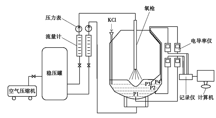
1.2 实验装置本实验以某厂55 t转炉为原型,图 1为有机玻璃制作的转炉模型及相关实验装置。转炉原型和模型几何尺寸与操作参数见表 1,原型与模型的物性参数见表 2。
|
图 1 复吹转炉水模拟实验装置 Figure 1 BOF water simulation apparatus |
| 表 1 原型与模型的几何尺寸与操作参数 Table 1 Physical dimension and operation parameters of the protype and the model |
| 表 2 原型与模型的物性参数 Table 2 Physical parameters of the protype and the model |
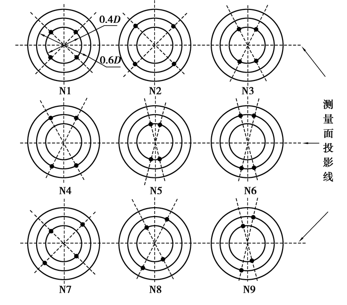
本实验在参考数值模拟结果[7-9]的基础上,选取熔池内不同位置的P1, P2, P3, P4点作为测量点,其中P1位于底部中心处, P2位于下侧壁面处,P3位于熔池内部r=0.6 R0,h=0.4L0的环流中心处(R0为熔池直径,L0为熔池深度,r为距转炉中心距P3点的水平距离,h为液面到P3点的垂直距离),P4位于上侧壁面处。4个测量点和转炉轴线共面,其所在平面与耳轴垂直,在有底吹参与的搅拌过程中,为了避免不同底吹喷嘴布置方式对实验结果的影响,使测量面过相邻较远的2个喷嘴与圆心所成夹角的对角线,以保证测量位置始终位于搅拌效果较差的区域,如图 2所示。
|
图 2 转炉底吹喷嘴的布置方案 Figure 2 Layout scheme of the bottom blowing nozzle |
用0.2 g/mL的KCl溶液作为示踪剂,每次加入量为30 mL;从示踪剂加入开始计时,直到各点的电导率测量值与稳定值之差达到±5%之内的时间视为混匀时间[15],4个测点的平均值视为平均混匀时间,其中混匀时间用来评价测点附近的混匀效果,平均混匀时间评价熔池整体的混匀效果;每次试验重复3次,取其平均值,测量点和示踪剂加入位置如图 1所示。
图 2中N1~N9为9个不同的底吹布置方式示意图,熔池直径为D,底吹喷嘴布置在0.4D和0.6D的圆周上,其中N1~N6为对称布置,N7~N9为非对称布置。
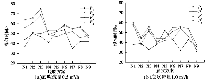
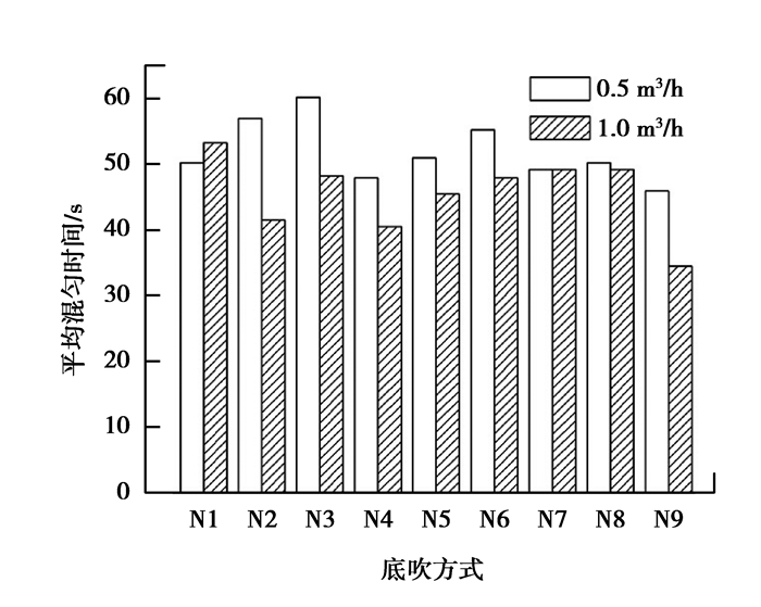
2 结果与讨论 2.1 底吹下的局部混匀效果纯底吹条件下,底吹流量分别取0.5 m3/h和1.0 m3/h时,各底吹方案的局域混匀时间如图 3所示。9种底吹布置方式中,喷嘴均关于底部中心对称,上升气流的搅拌作用在底部中心产生叠加,使底部中心附近传质加快,故P1附近混匀效果较好。图 4为各底吹方案下4个测点处的平均混匀时间,结合图 3和图 4可知,底吹流量由0.5 m3/h增大到1.0 m3/h时,混匀时间变短,且在所有底吹布置方案中,非对称布置的N9平均混匀时间最短,熔池整体搅拌效果最好。与对称布置方式相比,底吹喷嘴非对称布置时,相邻喷嘴位于在不同直径的圆周上,可以扩大径向上的搅拌范围,此外,两个喷嘴集中布置可以强化区域的搅拌效果。比较不同底吹方式下的混匀时间可知:纯底吹条件下,底吹方式对转炉混匀时间影响很大,底吹喷嘴非对称且相对集中布置时可获得更好的搅拌效果。
|
图 3 不同底吹流量下局域混匀时间与底吹方式的关系 Figure 3 Relationship between local mixing time and bottom-blowing ways at different bottom blowing flow |
|
图 4 平均混匀时间与底吹方式的关系 Figure 4 Relationship between local mixing time and bottom blowing ways |
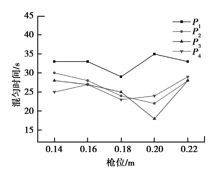
纯顶吹时,不同枪位下的局域混匀时间如图 5所示。从图中可以看到底部中心P1附近的混匀最长,搅拌效果最差;这是因为在只有顶吹的条件下,高速射流与液面发生弹性碰撞,冲击形成凹坑,水平切向的动量以环流的形式很难传递到熔池底部中心附近。随着枪位的升高,4个测点处的混匀时间呈先减小后增大的趋势,枪位在0.18 m附近时,P4点处混匀时间最短,0.20 m时P2和P3处搅拌最好。
|
图 5 局部混匀时间与枪位的关系 Figure 5 Relationship between local mixing time and lance height |
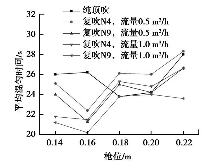
图 6为4个测点在不同喷吹条件下平均混匀时间随枪位的变化曲线,选择纯底吹时平均混匀时间最短的N4和N9两种底吹方式。从图中可以看到,复吹时,相同底吹流量下,底吹方式为为N9时平均混匀时间更短,说明底吹方式N9可以起到改善搅拌效果的作用;同一底吹方式下,底吹流量由0.5 m3/h增加到1.0 m3/h时,平均混匀时间变短,故一定程度上增大底吹流量可以缩短熔池的混匀时间。随着枪位的升高,平均混匀时间先减小后增大;当枪位为0.16 m时,平均混匀时间最短,说明该枪位下熔池整体混匀效果最好。当枪位处于0.14 m和0.16 m时,复吹下的熔池整体混匀效果优于纯顶吹,当枪位在0.18 m和0.20 m时,不同喷吹方式下的平均混匀时间差异不明显;当枪位为0.22 m,底吹方式N9流量1.0 m3/h的复吹平均混匀时间最短。
|
图 6 不同喷吹条件下平均混匀时间与枪位下的关系 Figure 6 Relationship between average mixing time and lance height at different blowing ways |
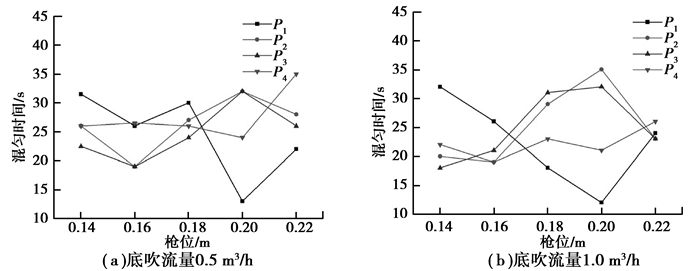
图 7为顶底复吹条件下,N9底吹布置方式中各测点处的混匀时间随枪位的变化情况。从图中可以看到,与纯顶吹相比,由于底吹的作用,相同位置的混匀时间差异很大,底部中心P1附近的搅拌效果明显改善;随着枪位的升高,4个测点处的混匀时间变化较大,枪位在0.20 m时,P1处的混匀时间最短,枪位为0.16 m时,P2,P3,P4处的搅拌效果最好。
|
图 7 方案N9在不同底吹流量下局部混匀时间与枪位的关系 Figure 7 Relationship between local mixing time and lance height at different bottom blowing flow of N9 |
1) 在转炉熔池搅拌过程中,不同区域的混匀时间各不相同;不同枪位下,搅拌弱区的位置随枪位变化;多点测量的方法能够在测得转炉局域混匀时间的同时对整体混匀效果做出评价。
2) 在纯底吹和顶底复吹条件下,底吹喷嘴布置方式对转炉混匀时间影响很大,与对称布置相比,底吹喷嘴非对称且相对集中布置时,局域混匀效果更好,混匀时间更短。
3) 在纯顶吹时,搅拌弱区在底部中心附近;顶底复吹时,局域混匀时间受枪位的影响很大,N9复吹下,随枪位的升高,4个测量点处的混匀时间先减小后增大,P1在枪位0.20 m时混匀时间最短,P2,P3,P4点在枪位0.16 m时混匀时间最短。
4) 本研究对优化复吹转炉内流场,减少局部搅拌弱区,确定最佳底吹喷嘴布置方式,具有一定的指导意义。
| [1] | Ajmani S K, Chatterjee A. Cold model studies of mixing and mass transfer in steelmaking vessels[J]. Ironmaking & Steelmaking , 2005, 32 (6) : 515–527. |
| [2] | Martín M, Rendueles M, Díaz M. Global and local mixing determinations for steel converter analysis[J]. Chemical Engineering Science , 2005, 60 (21) : 5781–5791. DOI:10.1016/j.ces.2005.05.017 |
| [3] |
包明丽, 刘坤, 吕国成, 等.
180 t转炉底吹气体与熔池相互作用的水模型实验[J]. 特殊钢 , 2008, 29 (2) : 18–20.
BAO Mingli, LIU Kun, LU Guocheng, et al. Water modelling test on interaction between injection gas and bath for an 180t converter[J]. Special Steel , 2008, 29 (2) : 18–20. (in Chinese) |
| [4] |
文光华, 唐萍, 闫广庭.
顶、底吹氧及天然气复吹转炉熔池搅拌能的分析[J]. 重庆大学学报:自然科学版 , 1991, 14 (6) : 32–37.
WEN Guanghua, TANG Ping, YAN Guangting. An analysis of stirring energy of bottom-blown O2 and CH4 in the combined-blown converter[J]. Journal of Chongqing University:Natural Science Edition , 1991, 14 (6) : 32–37. (in Chinese) |
| [5] | Lai Z Y, Xie Z, Zhong L C. Influence of bottom tuyere configuration on bath stirring in a top and bottom combined blown converter[J]. Journal of the Iron and Steel Institute of Japan , 2008, 48 (6) : 793–798. DOI:10.2355/isijinternational.48.793 |
| [6] |
王楠, 陈敏, 刘江伟, 等.
50 t复吹转炉底透气砖布置的水模实验研究[J]. 过程工程学报 , 2008, 8 (sup1) : 236–239.
WANG Nan, CHEN Min, LIU Jiangwei, et al. Water modeling of bottom blown elements layout for 50 t top-bottom combined blown converter[J]. The Chinese Journal of Process Engineering , 2008, 8 (sup1) : 236–239. (in Chinese) |
| [7] | Xu D, Cang D Q, Qin L X, et al. Mixing effect and energy efficiency analysis for different lances in steel converter process[J]. Advanced Materials Research , 2011 (317/318/319) : 1462–1473. |
| [8] |
温良英, 周远华, 陈登福, 等.
复吹转炉熔池内流体流动的数值模拟[J]. 重庆大学学报:自然科学版 , 2006, 29 (1) : 49–52.
WEN Liangying, ZHOU Yuanhua, CHENG Demhfu, et al. Numerical simulation of fluid flow in converter combined blown bath[J]. Journal of Chongqing University:Natural Science Edition , 2006, 29 (1) : 49–52. (in Chinese) |
| [9] | Lv M, Zhu R, Guo Y G, et al. Simulation of flow fluid in the BOF steelmaking Process[J]. Metallurgical and Materials Transactions B , 2013, 44 (6) : 1560–1571. DOI:10.1007/s11663-013-9935-4 |
| [10] |
曾亚楠, 李俊国, 韩志杰, 等.
唐钢50 t复吹转炉水模型的实验研究[J]. 特殊钢 , 2010, 31 (2) : 21–24.
ZENG Yanan, LI Junguo, HAN Zhijie, et al. Experimental study on water model for a 50 t top and bottom combined blown converter at Tangsteel[J]. Specail Steel , 2010, 31 (2) : 21–24. (in Chinese) |
| [11] |
李军成, 温良英, 陈登福, 等.
210 t双联复吹转炉水模拟实验研究[J]. 过程工程学报 , 2010, 10 (1) : 43–47.
LI Juncheng, WEN Liangyin, CHEN Dengfu, et al. Water-model study of a 210 t duplex combined blown converter[J]. The Chinese Journal of Process Engineering , 2010, 10 (1) : 43–47. (in Chinese) |
| [12] |
陈敏, 廖广福, 李光强, 等.
210 t顶底复吹转炉水模型实验研究[J]. 过程工程学报 , 2011, 11 (1) : 36–39.
CHEN Min, LIAO Guangfu, LI Guangqiang, et al. Water model study on a 210 t top bottom combined blown converter[J]. The Chinese Journal of Process Engineering , 2011, 11 (1) : 36–39. (in Chinese) |
| [13] | Tang P, Yu Y Y, Wen G H, et al. Study on the optimization of the combined blown converter process in Chongqing Iron and Steel Company[J]. Journal of University of Science and Technology Beijing, Mineral, Metallurgy, Material , 2008, 15 (1) : 5–9. DOI:10.1016/S1005-8850(08)60002-X |
| [14] | Singh V, Kumar J, Bhanu C, et al. A novel bottom stirring scheme to improve BOF performance through mixing and mass transfer modelling[J]. Journal of the Iron and Steel Institute of Japan , 2009, 49 (12) : 1889–1894. DOI:10.2355/isijinternational.49.1889 |
| [15] | Ternstedt P, Tilliander A, Jönsson P G, et al. Mixing time in a side-blown converte[J]. Journal of the Iron and Steel Institute of Japan , 2010, 50 (5) : 663–667. DOI:10.2355/isijinternational.50.663 |
 2015, Vol. 38


