b. 重庆大学 机械传动国家重点实验室, 重庆 400044
b. The State Key Laboratory of Mechanical Transmission, Chongqing University, Chongqing 400044, P. R. China
电动汽车通常采用高效率、高功率、高转矩密度的永磁电机作为驱动电机,其在动力匹配[1-4]、底盘结构等多个方面具有独特的优势[5],不需要减速机构、差速器、驱动桥等部件,更加节约能源,整车布置更加灵活[6-8]。电机的分析通常有3种方法:电路模拟法、磁场有限元法和场路耦合法[9-10]。电路模拟方法可以实现控制原理和控制算法的精确建模,但是很难准确地分析电机本体的固有特性,如磁路饱和、端部效应等,难以准确计及铁磁材料磁导率非线性的影响;磁场有限元分析方法可以综合考虑铁磁材料的非线性和转矩中的高次谐波,实现电机本体性能的精确分析,但它不能分析外电路为非标准激励的情况,不能全面分析不同控制策略下电机的动态性能;场路耦合法集成了电机的电磁场有限元模型和外部电路,利用时步有限元法模拟电机的动态过程[11-12],为分析电机设计方案和驱动控制系统之间的优化匹配提供有利的工具,提高了电机设计与分析的准确性和可靠性。文献[13]采用电磁场解析法建立永磁无刷直流电机及其驱动系统的动态仿真模型,将相反电势和电机的电感参数进行了理想化处理,未考虑到三相逆变桥输出电压中高次谐波的影响。文献[14]利用输入函数离散化的状态空间方法,仿真分析永磁无刷直流电机的稳态性能,缺点是未考虑铁磁材料的非线性以及输出转矩中高次谐波的影响。文献[15]采用数值解析法,将一台五相永磁式直线电机复杂的磁场问题简化为一系列非线性的拉普拉斯方程和泊松方程,其缺点是忽略了磁场涡流效应、端部效应以及定子开槽的影响,计算结果不够准确。文献[16]利用等效磁路法分析永磁同步电机,将复杂的电磁结构简化为一些等效磁路,该方法不能全面分析电机的磁场分布, 未考虑磁路饱和的影响。文献[17]考虑电感和永磁体磁链饱和的影响,建立永磁同步电机非线性d-q轴模型,进行开环运行仿真,得到电机的转速、电流、转矩等运行特性,但对外部电路进行了理想化处理。
针对上述电路模拟法、电磁场解析法和磁场有限元分析法存在的问题,笔者采用场路耦合法分析电动车用轮毂电机的效率特性。一方面可以计及磁路饱和以及端部效应等非线性因素的影响,另一方面可以考虑外部激励中时间谐波电流对磁场的影响,计算结果更接近实际情况。推导了轮毂电机电磁场与外电路耦合离散方程,计算了轮毂电机气隙负载感应电势、损耗分布以及效率特性,并通过实验验证计算结果的准确性。
1 场路耦合模型笔者研究的轮毂电机场路耦合分析模型主要包括电机瞬态磁场有限元方程、外部电路方程以及电磁转矩方程。
1.1 二维磁场有限元方程为简化计算,在进行电机电磁场分析时先做如下假设:
1) 忽略位移电流,认为电磁场是似稳场;
2) 材料为各向同性,忽略铁磁材料的磁滞效应;
3) 永磁体材料用等效面电流模拟;
4) 忽略电导率σ和磁导率μ的温度效应,它们仅为空间函数。
利用矢磁位描述场,瞬变电磁场的定解问题可以表达为
| $ \left\{ \begin{array}{l} \frac{\partial }{{\partial x}}\left( {\frac{1}{\mu }\frac{{\partial A}}{{\partial x}}} \right) + \frac{\partial }{{\partial y}}\left( {\frac{1}{\mu }\frac{{\partial A}}{{\partial y}}} \right) = - J + \sigma \frac{{{\rm{d}}A}}{{{\rm{d}}t}},\\ \frac{1}{\mu }\frac{{\partial A}}{{\partial n}}\left| {_{{l^ - }}} \right. + \frac{1}{\mu }\frac{{\partial A}}{{\partial n}}\left| {_{{l^ + }}} \right. = J,\\ A\left| {_{AB}} \right. = - A\left| {_{CD}} \right.,\\ A\left| {_{AC}} \right. = A\left| {_{BD}} \right. = 0, \end{array} \right. $ | (1) |
式中:
利用加权余量法建立有限元离散化方程,取权函数等于形状函数NT,对式(1)加权积分后再进行离散化得到瞬变电磁场的离散方程为
| $ \mathit{\boldsymbol{KA}} + \mathit{\boldsymbol{T\dot A}} = \mathit{\boldsymbol{CI}}, $ | (2) |
式中,
| $ \left\{ \begin{array}{l} {k_{ii}} = {b_i}{b_i} + {c_i}{c_i},\;\;\;\;\;\;\;\;\;{k_{ij}} = {k_{ji}} = {b_i}{b_j} + {c_i}{c_j},\\ {k_{jj}} = {b_j}{b_j} + {c_j}{c_j},\;\;\;\;\;\;\;{k_{jm}} = {k_{mj}} = {b_j}{b_m} + {c_j}{c_m},\\ {k_{mm}} = {b_m}{b_m} + {c_m}{c_m},\;\;\;\;\;{k_{mi}} = {k_{im}} = {b_m}{b_i} + {c_m}{c_i}。\end{array} \right. $ |
| $ \mathit{\boldsymbol{T}} = \sigma {S_\Delta }\left[ {\begin{array}{*{20}{c}} {1/6}&{1/12}&{1/12}\\ {1/12}&{1/6}&{1/12}\\ {1/12}&{1/12}&{1/6} \end{array}} \right], $ |
| $ \mathit{\boldsymbol{C}} = {\rm{diag}}\left( {\begin{array}{*{20}{c}} {\frac{{n{S_\Delta }}}{{3a{S_{\rm{b}}}}}}&{\frac{{n{S_\Delta }}}{{3a{S_{\rm{b}}}}}}&{\frac{{n{S_\Delta }}}{{3a{S_{\rm{b}}}}}} \end{array}} \right), $ |
式中:a为定子绕组并联支路数;n为槽中一个线圈边所含串联匝数;Sb为双层绕组的半槽面积。
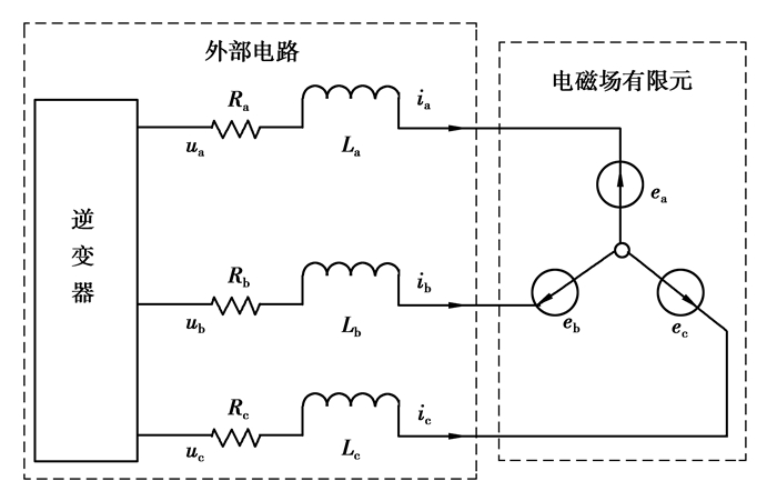
1.2 电磁场与外电路的耦合方程为了考虑外电路中时间谐波电流的影响,可用场路耦合法计算电磁瞬态过程,通过电枢绕组的电动势将电磁场有限元方程与绕组电路方程耦合起来,直接求解磁矢位和绕组电流。轮毂电机电枢绕组的等效电路如图 1所示。
|
图 1 轮毂电机耦合电路图 Figure 1 Coupled circuit diagram of in-wheel motor |
若绕组电动势都由线圈电动势组成,则A相绕组的电路方程为
| $ {u_{\rm{a}}} = {e_{\rm{a}}} + {R_{\rm{a}}}{i_{\rm{a}}} + {L_{\rm{a}}}\frac{{{\rm{d}}{i_{\rm{a}}}}}{{{\rm{d}}t}}。$ | (3) |
绕组电路方程的矩阵形式为
| $ \mathit{\boldsymbol{U}} = \mathit{\boldsymbol{E}} + \mathit{\boldsymbol{RI}} + \mathit{\boldsymbol{L\dot I}}。$ | (4) |
有限元区域的电动势可以通过绕组交链的磁通变化求得,相绕组电动势为磁链对时间的导数
| $ e = - \frac{{{\rm{d}}{\psi _{\rm{a}}}}}{{{\rm{d}}t}} = - \frac{{\rm{d}}}{{{\rm{d}}t}}\left( {\frac{{2n{L_{{\rm{ef}}}}p}}{{a{A_{\rm{b}}}}}\sum\limits_1^{{j_e}} {\sum\limits_{e = 1}^{{i_e}} {{A_{\rm{e}}}\frac{{{A_i} + {A_j} + {A_m}}}{3}} } } \right), $ | (5) |
式中:Lef为电枢铁心有效长度;je为每极每相槽数;ie为单元总数。
将式(5)转换为矩阵形式
| $ \mathit{\boldsymbol{E}} = - 2p{L_{{\rm{ef}}}}{\mathit{\boldsymbol{C}}^{\rm{T}}}\mathit{\boldsymbol{\dot A}}。$ | (6) |
综合三相感应电势、电压方程,将式(6)代入(4)可得离散方程
| $ \mathit{\boldsymbol{U}} = - 2p{L_{{\rm{ef}}}}{\mathit{\boldsymbol{C}}^{\rm{T}}}\mathit{\boldsymbol{\dot A}} + \mathit{\boldsymbol{RI}} + \mathit{\boldsymbol{L\dot I}}, $ | (7) |
式中:U =(ua ub uc)T为电压向量;I =(ia ib ic)T为电流向量;R =diag(Ra Rb Rc)为相绕组电阻矩阵;L =diag(La Lb Lc)为相绕组端部漏电感矩阵。
将电磁场方程式(2)和电路方程式(7)联立求解,得到场路耦合离散方程为
| $ \left[ {\begin{array}{*{20}{c}} \mathit{\boldsymbol{K}}&{ - \mathit{\boldsymbol{C}}}\\ {\bf{0}}&\mathit{\boldsymbol{R}} \end{array}} \right]\left\{ {\begin{array}{*{20}{c}} \mathit{\boldsymbol{A}}\\ \mathit{\boldsymbol{I}} \end{array}} \right\} + \left[ {\begin{array}{*{20}{c}} \mathit{\boldsymbol{T}}&{\bf{0}}\\ { - 2p{L_{{\rm{ef}}}}{\mathit{\boldsymbol{C}}^{\rm{T}}}}&\mathit{\boldsymbol{L}} \end{array}} \right]\left\{ {\begin{array}{*{20}{c}} {\mathit{\boldsymbol{\dot A}}}\\ {\mathit{\boldsymbol{\dot I}}} \end{array}} \right\}{\rm{ = }}\left[ {\begin{array}{*{20}{c}} {\bf{0}}\\ \mathit{\boldsymbol{U}} \end{array}} \right]。$ | (8) |
利用Crank-Nicolson方法对式(8)进行时间离散,得到整个场路方程耦合的空间和时间离散模型
| $ \left[ {\begin{array}{*{20}{c}} {{\mathit{\boldsymbol{K}}_{n + 1}} + \frac{2}{{\Delta t}}{\mathit{\boldsymbol{T}}_{n + 1}}}&\mathit{\boldsymbol{C}}\\ {{\mathit{\boldsymbol{C}}^{\rm{T}}}}&{\frac{{\Delta t\mathit{\boldsymbol{R}} + 2\mathit{\boldsymbol{L}}}}{{4p{L_{{\rm{ef}}}}}}} \end{array}} \right]\left\{ {\begin{array}{*{20}{c}} {{\mathit{\boldsymbol{A}}_{n + 1}}}\\ {{\mathit{\boldsymbol{I}}_{n + 1}}} \end{array}} \right\} = \left[ {\begin{array}{*{20}{c}} { - {\mathit{\boldsymbol{K}}_n} + \frac{2}{{\Delta t}}{\mathit{\boldsymbol{T}}_n}}&{\bf{0}}\\ {{\mathit{\boldsymbol{C}}^{\rm{T}}}}&{\frac{{\Delta t\mathit{\boldsymbol{R}} - 2\mathit{\boldsymbol{L}}}}{{4p{L_{{\rm{ef}}}}}}} \end{array}} \right]\left\{ {\begin{array}{*{20}{c}} {{\mathit{\boldsymbol{A}}_n}}\\ {{\mathit{\boldsymbol{I}}_n}} \end{array}} \right\} +\\ \left\{ \begin{array}{l} {\bf{0}}\\ \frac{{\Delta t\mathit{\boldsymbol{U}}}}{{2p{L_{{\rm{ef}}}}}} \end{array} \right\}。$ | (9) |
轮毂电机通常采用空间电压矢量控制策略,其基本思想是将定子的三相电流分解为磁场生成的分量(直轴d轴)和扭矩生成的分量(交轴q轴),然后对两个分量单独控制以实现对电机的控制。在d-q轴坐标系下,轮毂电机的瞬态电磁转矩为
| $ {T_{{\rm{em}}}} = \frac{p}{2}\left[ {\left( {{L_{{\rm{md}}}}{i_{{\rm{fd}}}}} \right){i_{{\rm{sq}}}} + \left( {{L_{{\rm{sd}}}} - {L_{{\rm{sq}}}}} \right){i_{{\rm{sd}}}}{i_{{\rm{sq}}}}} \right]。$ | (10) |
电机运动方程为
| $ J\frac{{{\rm{d}}{\omega _{\rm{m}}}}}{{{\rm{d}}t}} = {T_{{\rm{em}}}} - {T_1} - \beta {\omega _{\rm{m}}}。$ | (11) |
将其转化为离散形式
| $ {\omega _{\rm{m}}}\left( {t + \Delta t} \right) = \left[ {\frac{1}{{J + \beta \Delta t}}} \right]\left[ {J{\omega _{\rm{m}}}\left( t \right) + \Delta t\left( {{T_{{\rm{em}}}}\left( {t + \Delta t} \right) - {T_L}\left( {t + \Delta t} \right)} \right)} \right], $ | (12) |
式中:J为转子转动惯量;ωm为转子机械角速度;β为摩擦系数。
1.4 功率损耗模型电机损耗决定其效率,并且在很大程度上影响电机的运行成本,其定子绕组铜耗为
| $ {P_{{{\rm{C}}_{\rm{u}}}}} = 3{I^2}R。$ | (13) |
电机铁心损耗包括磁滞损耗、涡流损耗和附加损耗,考虑交变磁化的影响,采用经典的Bertotti铁耗计算模型
| $ {P_{{\rm{Fe}}}} = {P_{\rm{h}}} + {P_{\rm{c}}} + {P_{\rm{e}}} = {k_{\rm{h}}}fB_{\rm{m}}^2 + {k_{\rm{c}}}{f^2}B_m^2 + {k_{\rm{e}}}{f^{1.5}}B_{\rm{m}}^{1.5}, $ | (14) |
式中:kh,kc,ke分别为磁滞损耗系数、涡流损耗系数和异常涡流损耗系数;f为频率;Bm为磁通密度幅值。
当磁场变化时,永磁体内会感应出涡流而产生涡流损耗
| $ {P_{{\rm{mag}}}} = \sum\limits_k {\frac{{J_k^2}}{\sigma }{\rm{d}}v} , $ | (15) |
式中jk为k次谐波磁场在永磁体中感应的涡流密度。
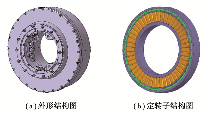
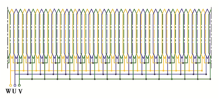
2 电机参数研究的轮毂电机为外转子永磁同步电机,表 1给出了轮毂电机主要技术参数,样机结构如图 2所示。为减小杂散损耗,削弱气隙磁场和感应电动势中的谐波,定子绕组为星形连接的双层叠绕组,如图 3所示。
| 表 1 轮毂电机主要参数 Table 1 Main parameters of in-wheel motor |
|
图 2 样机结构示意图 Figure 2 Prototype of in-wheel motor |
|
图 3 定子绕组连接图 Figure 3 Stator winding connection diagram |
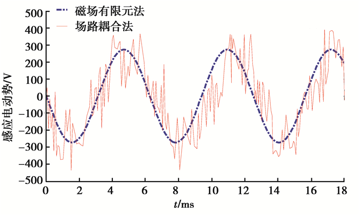
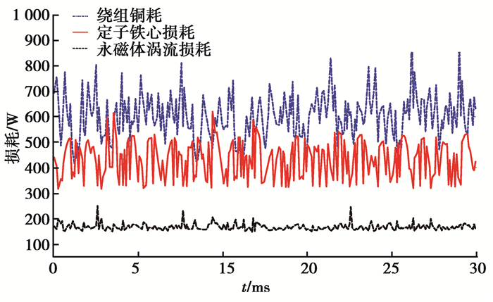
图 4给出了磁场限元法和场路耦合法计算的轮毂电机额定负载感应电动势曲线。磁场限元法将外部电路简化为理想的三相正弦信号,所以感应电动势也为标准的正弦信号,场路耦合法计算的负载感应电动势曲线中含有大量谐波,这是因为在变频调速系统中,轮毂电机由变频电源供电,除了基波以外,逆变器的输出电压中不可避免地包含非正弦波形式的高次谐波,导致感应电势曲线产生畸变,使电机内磁场产生大量谐波,进而产生相应的涡流损耗和谐波铁耗,使电机功率损耗升高,导致电机运行时效率降低,而磁场限元法未考虑外电路中电流谐波的影响,计算结果难以符合实际情况。图 5给出了场路耦合法计算的轮毂电机在额定工况运行时的损耗曲线,可以看出绕组铜耗所占比例较大,定子铁心损耗小于铜耗,永磁体涡流所占比例最小。损耗曲线中含有大量谐波分量。
|
图 4 负载感应电动势对比图 Figure 4 Comparison of load induced electromotive force |
|
图 5 额定工况运行时的损耗曲线 Figure 5 Loss curve at rated operating condition |
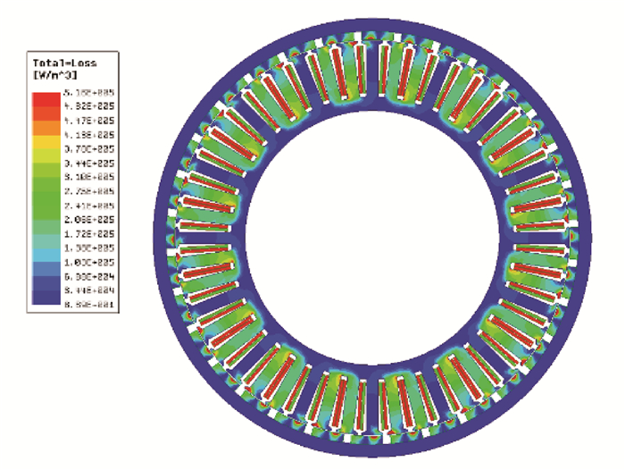
图 6为轮毂电机在额定工况运行时的瞬态损耗分布图。由图可知,在整个电机部件中,定子区域的整体损耗密度高于转子区域。损耗密度最高点位于定子绕组铜线上,这是由于定子绕组是一个大的功率损耗源,电机运行时会在绕组产生大量铜耗。定子硅钢片区域由于交变的磁场产生铁心损耗,其损耗密度略低于绕组区域。当电机工作于600 r/min时,电流变化频率为160 Hz,反向旋转的电枢反应谐波磁动势分量较强,会在表贴式的永磁体内部感应出较大的损耗,并产生永磁体涡流损耗。
|
图 6 额定工况时电机损耗分布 Figure 6 Distribution of motor loss at rated operating conditions |
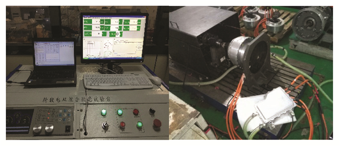
轮毂电机实验测试平台如图 7所示,主要由40 kW直流稳压稳流电源、上位机、驱动控制器、轮毂电机和国内某厂商的ET4110型号的测控系统组成。
|
图 7 轮毂电机实验测试平台 Figure 7 Test platform of in-wheel motor |
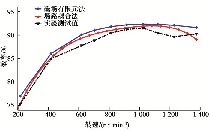
图 8为额定转矩和额定功率下轮毂电机效率与转速的关系曲线。可以看出在低速区,电机效率较低,当转速为200 r/min时,效率为75.26%;随着转速增大,电机效率先升高后降低,在1 000 r/min时,电机效率最高,为91.41%;在峰值转速时,电机效率为90.21%。整个过程中场路耦合法与实验测试值较接近,而磁场有限元法计算的效率值偏高,这是由于忽略了附加涡流损耗和附加铁耗所致。
|
图 8 额定转矩与额定功率运行时效率与转速的关系 Figure 8 Relationship between efficiency and rotational speed at rated torque and power |
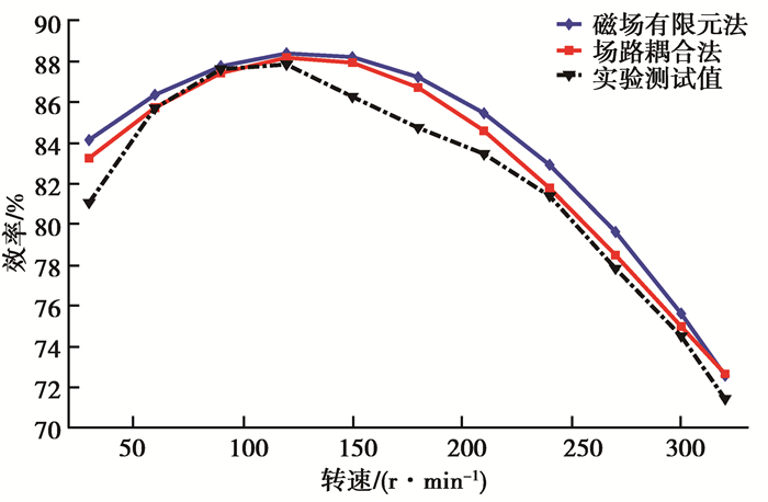
图 9为额定转速时轮毂电机效率与输出转矩的关系曲线。随着转矩的增大,电机效率升高,当转矩为120 N·m时,电机效率最高,为87.80%;随着转矩进一步增大,电机效率降低,当达到320 N·m的峰值转矩时,电机效率最低,为71.41%。场路耦合法计算结果能够较好地反应电机效率特性,与实验测试值较接近,而磁场限元法对外部输入作了理想化处理,忽略了电流谐波导致的附加损耗的影响,导致计算的效率值普遍偏高。
|
图 9 额定转速运行时效率与转矩的关系 Figure 9 The Relationship between efficiency and torque at rated speed |
为精确分析轮毂电机效率特性,给出一种电动车用轮毂电机场路耦合分析法,将电磁场与外电路方程联立求解。由于场路耦合法考虑了外电路中时间谐波电流的影响,使得负载感应电动势和功率损耗曲线产生畸变,进而产生附加涡流损耗和附加铁耗。通过实验对比分析轮毂电机在不同工况运行时的效率特性,表明场路耦合法计算结果更准确,而磁场有限元法对外部激励作了理想化处理,忽略了电流谐波的影响,计算结果偏高。
| [1] |
卢东斌, 欧阳明高, 谷靖, 等.
电动汽车永磁同步电机最优制动能量回馈控制[J]. 中国电机工程学报, 2013, 33(3): 83–91.
LU Dongbin, OUYANG Minggao, GU Jing, et al. Optimal regenerative braking control for permanent magnet synchronous motors in electric vehicles[J]. Proceedings of the CSEE, 2013, 33(3): 83–91. (in Chinese) |
| [2] |
唐任远, 赵清, 周挺.
稀土永磁电机正进入大发展的新时期[J]. 沈阳工业大学学报, 2011, 33(1): 1–8.
TANG Renyuan, ZHAO Qing, ZHOU Ting. Rare earth permanent magnet electrical machines stepping a new period of rapid development[J]. Journal of Shenyang University of Technology, 2011, 33(1): 1–8. (in Chinese) |
| [3] | Pangaribuan K A, Purwadi A. Performance analysis on EV mode of the 2012 toyota hybrid[C]//4th International Conference on Electrical Engineering and Informatics Procedia Technology, December 11-13, 2012, Procedia Technology, 2013:1065-1073. |
| [4] | Du B, Cui S, Han S, et al. A simple diagnosis of winding short-circuited fault of PMSM for electric vehicle[C]//2012 IEEE Vehicle Power and Propulsion Conference, October 9-12, 2012, seoul, Korea. IEEE, 2012:88-91. |
| [5] |
陈齐平, 舒红宇, 瞿飞俊, 等.
轮毂电机嵌入式电磁驻车制动设计与仿真[J]. 重庆大学学报, 2012, 35(7): 1–6.
CHEN Qiping, SHU Hongyu, QU Feijun, et al. Design and simulation of electromagnetic barriers embedded in-wheel motor[J]. Journal of Chongqing University, 2012, 35(7): 1–6. DOI:10.11835/j.issn.1000-582X.2012.07.001 (in Chinese) |
| [6] |
柴海波, 鄢治国, 况明伟, 等.
电动车驱动电机发展现状[J]. 微特电机, 2013, 41(4): 52–57.
CHAI Haibo, YAN Zhiguo, KUANG Mingwei, et al. The development status of driving motors for electrics vehicles[J]. Small & Special Electrical Machines, 2013, 41(4): 52–57. (in Chinese) |
| [7] |
舒红宇, 陈里敏, 陈齐平, 等.
轮毂电机嵌入式电磁离合器优化与动态分析[J]. 重庆大学学报, 2014, 37(5): 1–7.
SHU Hongyu, CHEN Limin, CHEN Qiping, et al. Optimization design and dynamic analysis for electromagnetic clutch in wheel hub motor[J]. Journal of Chongqing University, 2014, 37(5): 1–7. (in Chinese) |
| [8] |
褚文强, 辜承林.
电动车用轮毂电机研究现状与发展趋势[J]. 电机与控制应用, 2007, 34(4): 1–5.
CHU Wenqiang, GU Chenglin. Application status and developing tend of in-wheel motors used for electric automobile[J]. Electric Machines & Control Application, 2007, 34(4): 1–5. (in Chinese) |
| [9] | Zhu X, Chen M, Zhao W, et al. A transient cosimulation approach to performance analysis of hybrid excited doubly salient machine considering indirect field-circuit coupling[J]. IEEE Transactions on Magnetics, 2007, 43(6): 2558–2560. DOI:10.1109/TMAG.2007.893318 |
| [10] | Chen Y, Quan L, Zhu X, et al. Electromagnetic performance analysis of double-rotor stator permanent magnet motor for hybrid electric vehicle[J]. IEEE Transactions on Magnetics, 2012, 48(11): 4204–4207. DOI:10.1109/TMAG.2012.2206374 |
| [11] | Huangfu Y, Wang S, Qiu J, et al. Transient performance analysis of induction motor using field-circuit coupled finite-element method[J]. IEEE Transactions on Magnetics, 2014, 50(2): 873–876. DOI:10.1109/TMAG.2013.2281314 |
| [12] | Wang X, Xie D. Analysis of induction motor using field-circuit coupled time-periodic finite element method taking account of hysteresis[J]. IEEE Transactions on Magnetics, 2009, 45(3): 1740–1743. DOI:10.1109/TMAG.2009.2012802 |
| [13] |
王群京, 孙明施.
无刷直流电动机的动态仿真[J]. 合肥工业大学学报(自然科学版), 2000, 23(1): 53–56.
WANG Qunjing, SUN Mingshi. Dynamic simulat ion of BLDC motor[J]. Journal of Hefei University of Technology, 2000, 23(1): 53–56. (in Chinese) |
| [14] |
贺益康, 严岚.
永磁无刷直流电机稳态特性的状态空间分析[J]. 电工技术学报, 2002, 17(1): 17–22.
HE Yikang, YAN Lan. A state-space approach to steady-state performance of a permanent-magnet brushless DC motor[J]. Transactions of China Electrotechnical Society, 2002, 17(1): 17–22. (in Chinese) |
| [15] | Tomczuk B, Waindok A. A coupled field-circuit model of a 5-phase permanent magnet tubular linear motor[J]. Archives of Electrical Engineering, 2011, 60(1): 5–14. |
| [16] |
兰志勇, 杨向宇, 王芳媛, 等.
Taguchi方法在内嵌式正弦波永磁同步电机优化设计中的应用[J]. 电工技术学报, 2011, 26(12): 37–42.
LAN Zhiyong, YANG Xiangyu, WANG Fangyuan, et al. Application for optimal designing of sinusoidal interior permanent magnet synchronous motors by using the taguchi method[J]. Transactions of China Electrotechnical Society, 2011, 26(12): 37–42. (in Chinese) |
| [17] |
李景灿, 廖勇.
考虑饱和及转子磁场谐波的永磁同步电机模型[J]. 中国电机工程学报, 2011, 31(3): 60–66.
LI Jingcan, LIAO Yong. Model of permanent magnet synchronous motor considering saturation and rotor flux harmonics[J]. Proceedings of the CSEE, 2011, 31(3): 60–66. (in Chinese) |
 2017, Vol. 40


