压电材料可以通过不同的变形产生不同的电荷,也可以对其施加变化的电压而产生不同的变形,利用压电材料的这种智能特性可以制作传感装置和驱动装置。目前,应用较多的压电材料是压电晶体和压电陶瓷,但是,上述压电材料是脆性材料,柔韧性和弹性都很差,不能弯折,完全不能应用于球形和圆柱形等曲面结构。为此,国内外研发了一类新型压电材料——宏纤维复合材料(MFC, macro fiber composite)。MFC是将压电陶瓷制作成纤维状,然后和有机聚合物基按照不同的连通方式、体积比和空间分布复合而成。与传统的压电陶瓷相比,MFC具有极好的弯折特性、较高的耦合系数和良好的耐久性,这些优良性能使得MFC在弧形圆形板壳结构的减振降噪方面具有广阔的应用前景[1]。
要运用MFC对弧板结构进行振动控制,首先,需要了解MFC的力电关系,推导MFC复合弧板结构的作动方程,近些年,不少学者对MFC作动方程进行了研究。Zhang等[2]在Reissner-Mindlin理论的基础上,运用线性压电本构方程,建立了粘贴有MFC复合悬臂梁的有限元模型,研究了在常压下压电纤维不同的排列方式对悬臂梁变形的影响差异。Ma等[3]针对悬臂梁轴向运动产生的振动问题,运用Hamilton原理推导了梁轴向运动的自由振动方程,将MFC和主体结构分开考虑,把MFC对主体结构的作用当作外部控制力,从而简化了结构的作动方程,这为研究MFC复合结构作动方程提供了新思路。Dano等[4]用MFC对悬臂梁的热致变形进行主动控制,利用有限元软件完成了复合结构的建模并进行了实验,结果表明,MFC对减小悬臂梁热致变形有显著效果。Kwak等[5]基于Donnel-Mushtari壳理论,利用pin-force模型建立了MFC复合圆柱壳的作动方程,认为MFC为结构提供了等效作用力,该公式只考虑了MFC压电系数、弹性模量和外加电场强度3个因素,只单纯考虑了MFC的作用力,并未考虑MFC和主结构之间的复合作用。Akash等[6]利用Kirchhoff板理论建立了二维MFC板单元动力学模型,并将其与Mindlin板理论模型和实验结果进行了对比,证明了该建模方法的有效性。Gangolu等[7]利用MFC对一弧形壳进行主动控制,基于一阶剪切变形理论,建立了四节点复合面-壳单元,运用有限元法推导出MFC弧形壳的动力学模型,但没有得到确切的MFC力电关系。
基于以上研究,推导了考虑MFC和受控结构之间的复合作用以及MFC受弧板曲率影响产生的径向作动力的作动方程,得到了精确的MFC力电关系。在此基础上进行了关于弧板结构的振动控制仿真,并完成了主动控制试验。
1 宏纤维复合弧板结构的作动方程MFC复合弧板结构的作动方程是基于MFC的第一类压电方程推导的。通过对第一类压电方程的变换得到MFC中的应力,再根据应力方程推导出MFC复合弧板结构的作动方程,进而计算出MFC对弧板结构的作动力和作动弯矩。
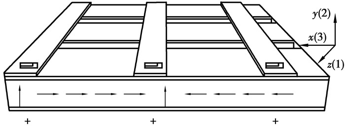
1.1 MFC的压电方程将MFC作动层视为均质的压电纤维,如图 1所示。在x轴方向极化的MFC线弹性压电材料的本构方程可以写成[8]:
|
图 1 MFC的单元结构 Figure 1 Unit Structure of MFC |
| $ \left[ {\begin{array}{*{20}{c}} {{\varepsilon _z}}\\ {{\varepsilon _y}}\\ {{\varepsilon _x}}\\ {{\gamma _{yx}}}\\ {{\gamma _{xz}}}\\ {{\gamma _{zy}}} \end{array}} \right] = \left[ {\begin{array}{*{20}{c}} {s_{11}^E}&{s_{12}^E}&{s_{13}^E}&0&0&0\\ {s_{21}^E}&{s_{22}^E}&{s_{23}^E}&0&0&0\\ {s_{31}^E}&{s_{32}^E}&{s_{33}^E}&0&0&0\\ 0&0&0&{s_{44}^E}&0&0\\ 0&0&0&0&{s_{55}^E}&0\\ 0&0&0&0&0&{s_{66}^E} \end{array}} \right]\left[ {\begin{array}{*{20}{c}} {{\sigma _z}}\\ {{\sigma _y}}\\ {{\sigma _x}}\\ {{\tau _{yx}}}\\ {{\tau _{xz}}}\\ {{\tau _{zy}}} \end{array}} \right] + \left[ {\begin{array}{*{20}{c}} 0&0&{{d_{31}}}\\ 0&0&{{d_{32}}}\\ 0&0&{{d_{33}}}\\ 0&{{d_{24}}}&0\\ {{d_{15}}}&0&0\\ 0&0&0 \end{array}} \right]\left[ {\begin{array}{*{20}{c}} 0\\ 0\\ {{E_x}} \end{array}} \right], $ | (1) |
式中:sijE为MFC的柔度系数,其中i表示MFC的应变方向,j表示MFC的应力方向;dij为MFC的压电应变系数,其中i表示电场作用方向,j表示受到电场作用后压电材料的应变方向,1、2、3分别对应于笛卡尔坐标系下的z、y、x方向,4、5、6分别对应于笛卡尔坐标系下的剪切变形方向yx、xz、zy;Ex为x方向的电场强度。
MFC形状为薄片状,厚度只有0.3 mm,可以忽略厚度方向,即忽略y方向的应力与应变。MFC剪切应变γzx与电场强度Ex无关,并且MFC本身的剪切应变τxz也很小,可以忽略剪切应变的影响,公式可简化为
| $ \left[ {\begin{array}{*{20}{c}} {{\varepsilon _z}}\\ {{\varepsilon _x}} \end{array}} \right] = \left[ {\begin{array}{*{20}{c}} {s_{11}^E}&{s_{13}^E}\\ {s_{13}^E}&{s_{33}^E} \end{array}} \right]\left[ {\begin{array}{*{20}{c}} {{\sigma _z}}\\ {{\sigma _x}} \end{array}} \right] + \left[ {\begin{array}{*{20}{c}} {{d_{31}}}\\ {{d_{33}}} \end{array}} \right]{E_x}, $ | (2) |
式中,MFC内的电场强度Ex为
| $ {E_x} = \frac{V}{w}, $ | (3) |
其中:V为施加的电压幅值;w为MFC电极丝插值电极间距。
MFC的柔度系数s33E可表示为
| $ s_{33}^E = \frac{1}{{{E_f}}}, $ | (4) |
其中,Ef为MFC的弹性模量。
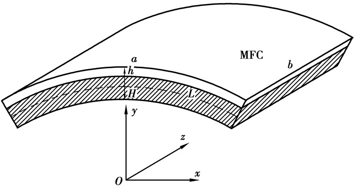
1.2 二维MFC复合弧板的作动方程二维MFC复合弧板结构,如图 2所示。板的厚度为H;MFC有效长度为a、宽度为b、厚度为h;L为结构中性轴距离受控结构上表面的距离,由于MFC厚度极小,故近似令L=0.5H。
|
图 2 MFC复合弧板的单元结构 Figure 2 Unit structure of composite arc plate |
由公式(3)可知二维MFC的应力为
| $ \left[ {\begin{array}{*{20}{c}} {{\sigma _z}}\\ {{\sigma _x}} \end{array}} \right] = \left[ {\begin{array}{*{20}{c}} {\mathit{\boldsymbol{Q}}_{11}^E}&{\mathit{\boldsymbol{Q}}_{13}^E}\\ {\mathit{\boldsymbol{Q}}_{31}^E}&{\mathit{\boldsymbol{Q}}_{33}^E} \end{array}} \right]\left[ {\begin{array}{*{20}{c}} {{\varepsilon _z} - {d_{31}}{E_x}}\\ {{\varepsilon _x} - {d_{33}}{E_x}} \end{array}} \right], $ | (5) |
其中,矩阵QE是矩阵sE的逆矩阵
| $ \mathit{\boldsymbol{Q}}_{11}^E = \frac{{\mathit{\boldsymbol{s}}_{33}^E}}{{\mathit{\boldsymbol{s}}_{11}^E\mathit{\boldsymbol{s}}_{33}^E - {{\left( {\mathit{\boldsymbol{s}}_{13}^E} \right)}^2}}},\mathit{\boldsymbol{Q}}_{13}^E = \mathit{\boldsymbol{Q}}_{31}^E = \frac{{ - \mathit{\boldsymbol{s}}_{13}^E}}{{\mathit{\boldsymbol{s}}_{11}^E\mathit{\boldsymbol{s}}_{33}^E - {{\left( {\mathit{\boldsymbol{s}}_{13}^E} \right)}^2}}},\mathit{\boldsymbol{Q}}_{33}^E = \frac{{\mathit{\boldsymbol{s}}_{11}^E}}{{\mathit{\boldsymbol{s}}_{11}^E\mathit{\boldsymbol{s}}_{33}^E - {{\left( {\mathit{\boldsymbol{s}}_{13}^E} \right)}^2}}} $ | (6) |
二维柔度矩阵可表示为
| $ \left[ {\begin{array}{*{20}{c}} {\mathit{\boldsymbol{s}}_{11}^E}&{\mathit{\boldsymbol{s}}_{13}^E}\\ {\mathit{\boldsymbol{s}}_{31}^E}&{\mathit{\boldsymbol{s}}_{33}^E} \end{array}} \right] = \left[ {\begin{array}{*{20}{c}} {\frac{1}{{{E_f}}}}&{\frac{{ - {\mu _f}}}{{{E_f}}}}\\ {\frac{{ - {\mu _f}}}{{{E_f}}}}&{\frac{1}{{{E_f}}}} \end{array}} \right], $ | (7) |
其中,μs为MFC的泊松比。
MFC对二维弧板结构的单位长度作动弯矩为
| $ \left. \begin{array}{l} {M_{z0}} = \int_L^{L + h} {\left( { - {\sigma _z}} \right)y{\rm{d}}y} = \\ \;\;\;\;\;\;\;\;\;\;\int_L^{L + h} {\left[ {Q_{11}^E\left( {{d_{31}}{E_x} - {\varepsilon _z}} \right) + Q_{13}^E\left( {{d_{33}}{E_x} - {\varepsilon _\theta }} \right)} \right]y{\rm{d}}y} \\ {M_{\theta 0}} = \int_L^{L + h} {\left( { - {\sigma _\theta }} \right)y{\rm{d}}y} = \\ \;\;\;\;\;\;\;\;\;\;\int_L^{L + h} {\left[ {Q_{31}^E\left( {{d_{31}}{E_x} - {\varepsilon _z}} \right) + Q_{33}^E\left( {{d_{33}}{E_x} - {\varepsilon _\theta }} \right)} \right]y{\rm{d}}y} \end{array} \right\}, $ | (8) |
由弯曲变形理论可知,二维MFC复合结构的应变可以由弯矩Mx与Mz表示:
| $ \left[ {\begin{array}{*{20}{c}} {{\varepsilon _z}}\\ {{\varepsilon _\theta}} \end{array}} \right] = \left[ {\begin{array}{*{20}{c}} {\frac{{{M_z}y}}{{{E_p}{I_{pz}}}} - \frac{{{\mu _p}{M_\theta }y}}{{{E_p}{I_{p\theta }}}}}\\ {\frac{{{M_\theta }y}}{{{E_p}{I_{p\theta }}}} - \frac{{{\mu _p}{M_z}y}}{{{E_p}{I_{pz}}}}} \end{array}} \right], $ | (9) |
其中:Ep为受控结构的弹性模量;Ipθ、Ipz分别为弧板结构横截面绕MFC横向与纵向中性层的惯性矩。将式(9)代入式(8)可以求得
| $ \left. \begin{array}{l} {M_{z0}} = \frac{{A{E_p}{E_x}{I_{pz}}\left( {\left( {{d_{31}} + {\mu _p}{d_{33}}} \right)C + {d_{31}}{Q_{11}} + {d_{33}}{Q_{13}}} \right)}}{{E_p^2{I_{px}}{I_{pz}} + BC\left( {1 - \mu _p^2} \right) + B\left( {{Q_{11}} + {Q_{33}} - {\mu _p}{Q_{31}} - {\mu _p}{Q_{13}}} \right)}}\\ {M_{\theta 0}} = \frac{{A{E_p}{E_x}{I_{px}}\left( {\left( {{d_{33}} + {\mu _p}{d_{31}}} \right)C + {d_{33}}{Q_{33}} + {d_{31}}{Q_{31}}} \right)}}{{E_p^2{I_{px}}{I_{pz}} + BC\left( {1 - \mu _p^2} \right) + B\left( {{Q_{11}} + {Q_{33}} - {\mu _p}{Q_{31}} - {\mu _p}{Q_{13}}} \right)}} \end{array} \right\}, $ | (10) |
其中:
| $ A = \frac{{{{\left( {L + h} \right)}^2} - {L^2}}}{2};B = \frac{{{{\left( {L + h} \right)}^3} - {L^3}}}{3}; $ |
| $ C = B\left( {Q_{11}^EQ_{33}^E - Q_{13}^EQ_{31}^E} \right); $ |
| $ {\mathit{\boldsymbol{Q}}_{11}} = {E_p}{I_{px}}\mathit{\boldsymbol{Q}}_{11}^E、{\mathit{\boldsymbol{Q}}_{13}} = {E_p}{I_{px}}\mathit{\boldsymbol{Q}}_{13}^E; $ |
| $ {\mathit{\boldsymbol{Q}}_{31}} = {E_p}{I_{pz}}\mathit{\boldsymbol{Q}}_{31}^E、{\mathit{\boldsymbol{Q}}_{33}} = {E_p}{I_{pz}}\mathit{\boldsymbol{Q}}_{33}^E。$ |
因此,MFC对二维板结构的单位长度作动力为
| $ \left. \begin{array}{l} {F_{z0}} = - \int_L^{L + h} {{\sigma _z}{\rm{d}}y} = \\ \;\;\;\;\;\;\;\int_L^{L + h} {\left[ {Q_{11}^E\left( {{d_{21}}{E_x} - {\varepsilon _z}} \right) + Q_{13}^E\left( {{d_{33}}{E_x} - {\varepsilon _\theta }} \right)} \right]{\rm{d}}y} \\ {F_{\theta 0}} = - \int_L^{L + h} {{\sigma _\theta }{\rm{d}}y} = \\ \;\;\;\;\;\;\;\int_L^{L + h} {\left[ {Q_{31}^E\left( {{d_{31}}{E_x} - {\varepsilon _z}} \right) + Q_{33}^E\left( {{d_{33}}{E_x} - {\varepsilon _\theta }} \right)} \right]{\rm{d}}y} \end{array} \right\}, $ | (11) |
化简式(11)可得
| $ \left. \begin{array}{l} {F_{z0}} = \left( {{d_{31}}Q_{11}^E + {d_{33}}Q_{13}^E} \right)h{E_x} + \frac{{A{M_{z0}}\left( {{\mu _p}Q_{13}^E - Q_{11}^E} \right)}}{{{E_p}{I_{pz}}}} + \frac{{A{M_{\theta 0}}\left( {{\mu _p}Q_{11}^E - Q_{13}^E} \right)}}{{{E_p}{I_{p\theta }}}}\\ {F_{\theta 0}} = \left( {{d_{31}}Q_{31}^E + {d_{33}}Q_{33}^E} \right)h{E_x} + \frac{{A{M_{z0}}\left( {{\mu _p}Q_{33}^E - Q_{31}^E} \right)}}{{{E_p}{I_{pz}}}} + \frac{{A{M_{\theta 0}}\left( {{\mu _p}Q_{31}^E - Q_{33}^E} \right)}}{{{E_p}{I_{p\theta }}}} \end{array} \right\}, $ | (12) |
MFC对二维弧板结构的环向单位面积的径向作动力为
| $ \int_0^\gamma {{F_{r0}}R\cos \left( {\frac{{\gamma - 2\theta }}{2}} \right){\rm{d}}\theta } = 2{F_{\theta 0}}\sin \left( {\frac{\gamma }{2}} \right), $ |
| $ {F_{r0}} = \frac{{{F_{\theta 0}}}}{R}, $ |
其中:R为弧板半径;γ为MFC的所占的弧度。
2 MFC复合弧板结构作动方程的试验验证为了验证推导的MFC复合弧板结构作动方程的正确性,将P1/d33型MFC粘贴于弧板结构上,完成了仿真模拟和振动控制试验。
首先, 利用ANSYS有限元软件进行弧板结构建模,弧板模型的建模参数如表 1所示。然后, 定义激振力与MFC的作动力与作动弯矩,将激振力的激振位置设置在弧板中心,MFC的作用位置如图 3的黑线位置所示。MFC与弧板结构复合所产生的作动力与作动弯矩为文中第二部分推导求得,将计算得到的Fθ0、Fz0与Mx0、Mz0施加在图 3中黑线所在位置的节点处,将计算得到的径向作动力Fr0施加在黑线包围位置的各个节点处。在仿真模拟中,激振力与MFC的作动力均为简谐力,且激振力与MFC作动力与作动弯矩所产生的位移相位相反,这样MFC的作动力与作动弯矩可以起到减小振动的作用。仿真模拟中激振力共3种工况,分别为20 Hz、10 N,50 Hz、10 N与100 Hz、10 N,MFC的工作电压为300 V。
| 表 1 材料属性 Table 1 Material properties |

|
图 3 MFC复合弧板结构的ANSYS模型 Figure 3 ANSYS model of composite arc plate structure |
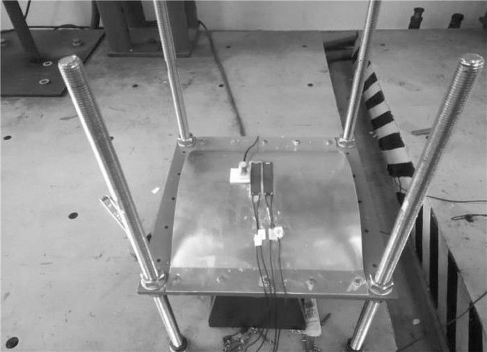
在MFC复合弧板振动控制试验中,弧板与MFC的参数与仿真一致。试验中主要仪器有加速度传感器、MFC、激振器、功率放大器和dSPACE实时仿真系统等,试验系统如图 4所示。其中, 加速度传感器自重相对较轻,对试验结果与模拟结果差异的影响可忽略不计。试验通过dSPACE输出频率为20、50,100 Hz的3种正弦信号为激振器与MFC提供激励信号,且激振器与MFC的信号相位相反,通过加速度传感器获得加速度信号,试验模型如图 5所示。

|
图 4 MFC复合弧板试验系统 Figure 4 Test system of MFC composite arc plate |
|
图 5 MFC复合弧板试验模型 Figure 5 Test model of MFC composite arc plate |
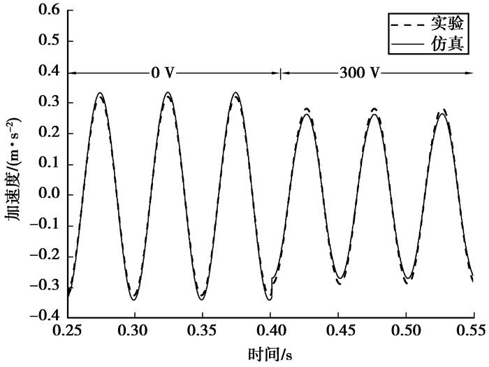
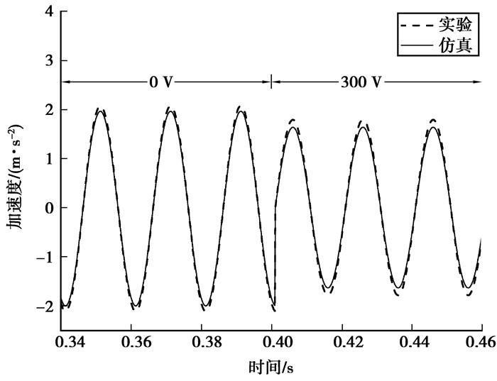
图 6~图 8比较了不同工况下仿真模拟和实际试验的加速度时程。从图中可以明确看到,在3种工况下,仿真结果与试验结果的偏差均在8.5%以内,因此, 文中推导的MFC复合弧板结构的作动方程可以正确描述MFC的力电关系。当激振力为20 Hz、10 N与工作电压为300 V时,试验中单片MFC可以使加速度幅值减小9.54%;当激振力为50 Hz、10 N与工作电压为300 V时,单片MFC可以使加速度幅值减小12.68%;当激振力为100 Hz、10 N与工作电压为300 V时,单片MFC可以使加速度幅值减小15.44%。由此可知,MFC可以有效地减小弧板结构振动,对于高频振动尤为明显。
|
图 6 20 Hz弧板试验与仿真结果对比 Figure 6 Comparison of arc plate test and simulation results with 20 Hz |
|
图 7 50 Hz弧板试验与仿真结果对比 Figure 7 Comparison of arc plate test and simulation results with 50 Hz |

|
图 8 100 Hz弧板试验与仿真结果对比 Figure 8 Comparison of arc plate test and simulation results with 100 Hz |
文中推导了MFC复合弧板结构的作动方程,并通过仿真与试验加以验证。
1) 推导的二维MFC复合弧板结构作动方程考虑了MFC与弧板结构的复合作用以及MFC在弧板结构曲率影响下产生的径向作动力,使得MFC对弧板作用的力电关系更加精确实用。
2) 完成了MFC对弧板结构振动的主动控制仿真与试验。通过仿真模拟与试验验证,得到了在20 Hz、10 N与50 Hz、10 N激励下仿真与试验的控制前后对比结果。在20 Hz、10 N, 50 Hz、10 N与100 Hz、10 N的工况下,仿真与试验的偏差在8.5%以内。研究结果进一步证明了文中给出的MFC作动方程是正确的,适用于弧板结构,还表明了MFC对弧板结构的振动控制具有良好的效果。
| [1] | Williams B R, Park G, Inman D J, et al. An overview of composite actuators with piezoceramic fibers[C]. LosAngles: CA. Proceedings of 20th International Modal Analysis Conference, February 4-7, 2002. |
| [2] | Zhang S Q, Rüdiger S. Modeling and simulation ofmacro-fiber composite layered smart structures[J]. Compos Struct, 2015, 126: 89–100. DOI:10.1016/j.compstruct.2015.02.051 |
| [3] | Ma G L, Minglong X, Zengyong A, et al. Active vibration control of an axially moving cantilever structure using MFC[J]. International Journal of Applied Electromagnetics and Mechanics, 2016, 52: 967–974. DOI:10.3233/JAE-162113 |
| [4] | Dano M L, Jullière B. Active control of thermally induced distortion in composite structures using Macro Fiber Composite actuators[J]. Smart Mater Struct, 2007, 16: 2315–2322. DOI:10.1088/0964-1726/16/6/035 |
| [5] | Kwak M K, Heo S, Jeong M. Dynamic modellingand active vibration controller design for a cylindrical shellequipped with piezoelectric sensors and actuators[J]. Journal ofSound and Vibration, 2009, 321(3/5): 510–524. |
| [6] | Akash P, Arockiarajan A. Actuation performance of macro-fiber composite (MFC):Modeling and experimental studies[J]. Sensors and Actuators, 2016, 248: 114–129. DOI:10.1016/j.sna.2016.07.022 |
| [7] | Gangolu V K, Samikkannu R, Karavadappa B P. Vall, Finite Element Analysis and Vibration Control of a Deep Composite Cylindrical Shell Using MFC Actuators[J]. Smart Materials Research, 2012(12): 12–24. |
| [8] | Sreenivasa S, Prasath A A. Effective electromechanical response of macro-fiber composite (MFC): analytical and numerical models[C]. [S. l. ]: Int. J. Mech. Sci. 77, 2013, 98-106. |
 2018, Vol. 41


