b. 重庆大学 汽车工程学院, 重庆 400044
b. College of Automotive Engineering, Chongqing University, Chongqing 400044, P. R. China
近年来,能源短缺和生态环境恶化问题日益突出,电动汽车以其零排放成为汽车产业的重要发展方向。其中,轮毂电机驱动电动汽车以其结构紧凑、驱动效率高和动力学可控性好等优点,成为国内外的研究热点。然而,全新的动力源布置形式会带来一系列新的动力学问题,主要体现在:由于传动系统弱阻尼特性,造成驱动电机电磁力输出与车辆动力学响应相互作用,带来车身、车轮共振,垂向动力学冲击响应等一系列振动负效应问题,影响电动汽车的平顺性和安全性。
针对轮毂驱动系统机电耦合效应,Wang等[1]提出轮毂电机驱动系统输出电机不平衡力由驱动电机定子与转子相对偏心造成,它对车辆垂向动力学响应和悬架性能有较大的影响[2]。Tan等[3]指出路面干扰会影响电机定转子的相对位移量,从而导致电机的定转子偏心。Sun等[4]通过电流绕组的振动反馈控制减小了不平衡电磁力对悬架舒适性的影响。Luo等[5]提出采用橡胶衬套来隔离轮毂电机的振动的方法[6]。以上方法从驱动电机控制和悬架构型再设计的角度,研究了振动负效应的间接控制方法,效果有限,而构型设计较为复杂,实际中开发难度较大。
电磁主动悬架系统能有效兼顾车辆的平顺性和操稳性,具有明显的动力学优势[7]。笔者采用傅立叶级数法,计算轮毂电机的不平衡径向力,建立考虑不平衡径向力的悬架系统机电耦合模型,通过对主动悬架系统构型及控制参数的多目标优化,有效抑制振动负效应,改善电动汽车的平顺性和安全性。
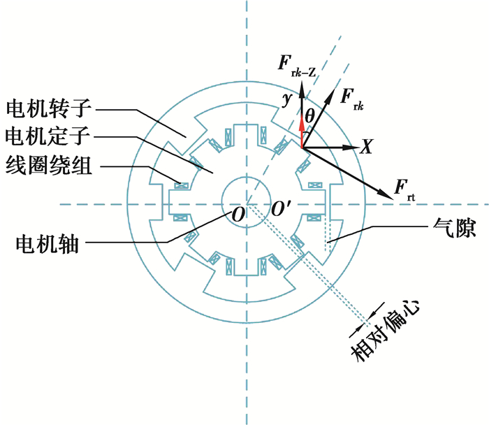
1 电机模型图 1为一个典型的8/6极外转子开关磁阻(SR)电机[8-10],由外转子、内定子、绕组线圈和支撑轴组成。通过外转子极气隙内定子极形成闭合磁路。额定功率为3 kW,额定电压为220 V,调速范围30~2 000 r/min。为了研究开关磁阻电机的不平衡径向力,采用傅立叶级数法建立SR电机的电磁多场统一特性方程。
|
图 1 电机模型 Figure 1 Motor model |
假设绕组间的互感忽略不计[11],相绕组间的磁共能Wm可以表示为
| $ {W_m} = \int_0^i {\psi \left( {\theta ,i} \right){\rm{d}}i} , $ | (1) |
式中θ为电机定、转子间的相对角位移,根据虚功原理和机电能量转换,电机第k相广义电磁力Fk可以表达为磁共能Wm与广义位移x的偏微分:
| $ {F_k} = \frac{{\partial {W_{\rm{m}}}}}{{\partial x}}\left| {_{i = {\rm{const}}}} \right. = \int_0^i {\frac{{\partial {\psi _k}\left( {\theta ,i} \right)}}{{\partial x}}{\rm{d}}i} 。$ | (2) |
当广义位移x为电机气隙Δg,则径向电磁力Fr为
| $ {F_r} = \frac{{\partial {W_{\rm{m}}}}}{{\partial {g_{\rm{m}}}}}\left| {_{i = {\rm{const}}}} \right. = \int_0^i {\frac{{\partial \psi \left( {\theta ,i} \right)}}{{\partial {g_{\rm{m}}}}}{\rm{d}}i} 。$ | (3) |
假设电机定、转子磁极不对齐位置为初始位置,此时角位移为0°。那么定、转子凸极间对齐位置为π/Nr,Nr为转子极数。此时,绕组电感L(θ, i)可写成傅立叶级数形式[12-13]:
| $ L\left( {\theta ,i} \right) = {L_0}\left( i \right) + {L_1}\left( i \right)\cos \left( {{N_{\rm{r}}}\theta + {\varphi _1}} \right) + \sum\nolimits_{n = 2,3, \cdots }^\infty {{L_n}\left( i \right)\cos \left( {n{N_{\rm{r}}}\theta + {\varphi _n}} \right)} \\ = \sum\nolimits_{n = 0}^\infty {{L_n}\left( i \right)\cos \left( {n{N_{\rm{r}}}\theta + {\varphi _n}} \right)} , $ | (4) |
式中φn=nπ,傅立叶系数Ln由各位置的绕组电感获得[14]。根据极与极对齐位置电感La、极与槽对齐位置电感Lu和极与槽半对齐位置电感Lm计算傅立叶系数,关系表达为
| $ \begin{array}{*{20}{c}} {{L_0}\left( i \right) = \frac{1}{2}\left[ {\frac{1}{2}\left( {{L_{\rm{a}}} + {L_{\rm{u}}}} \right) + {L_{\rm{m}}}} \right],}\\ {{L_1}\left( i \right) = \frac{1}{2}\left( {{L_{\rm{a}}} - {L_{\rm{u}}}} \right),}\\ {{L_2}\left( i \right) = \frac{1}{2}\left[ {\frac{1}{2}\left( {{L_{\rm{a}}} + {L_{\rm{u}}}} \right) - {L_{\rm{m}}}} \right]。} \end{array} $ | (5) |
当转子极不处于上述临界位置时,定、转子间气隙相对较大,假设Lu此时恒定不变[15]。La和Lm表达为
| $ \begin{array}{*{20}{c}} {{L_{\rm{a}}}\left( i \right)\left| {_{\theta = \frac{{\rm{ \mathsf{ π} }}}{{{N_{\rm{r}}}}}}} \right. = \sum\nolimits_{n = 0}^N {{a_n}{i^n}} ,}\\ {{L_{\rm{m}}}\left( i \right)\left| {_{\theta = \frac{{\rm{ \mathsf{ π} }}}{{2{N_{\rm{r}}}}}}} \right. = \sum\nolimits_{n = 0}^N {{b_n}{i^n}} 。} \end{array} $ | (6) |
代入公式(4),k相的绕组电感为
| $ \begin{array}{*{20}{c}} {{L_k}\left( {\theta ,{i_k}} \right) = \sum\nolimits_{n = 0}^\infty {{L_n}\left( {{i_k}} \right)\cos \left( {n{N_r}\theta + {\varphi _n}} \right)} = }\\ {\frac{1}{2}\left[ {{{\cos }^2}\left( {{N_{\rm{r}}}\theta } \right) - \cos \left( {{N_{\rm{r}}}\theta } \right)} \right]\sum\nolimits_{n = 0}^N {{a_n}i_k^n} + {{\sin }^2}\left( {{N_{\rm{r}}}\theta } \right)\sum\nolimits_{n = 0}^N {{b_n}i_k^n} + \frac{1}{2}{L_{\rm{u}}}\left[ {{{\cos }^2}\left( {{N_{\rm{r}}}\theta } \right) + \cos \left( {{N_{\rm{r}}}\theta } \right)} \right]。} \end{array} $ | (7) |
k相的绕组磁通量为
| $ \begin{array}{*{20}{c}} {\psi \left( {\theta ,{i_k}} \right) = \int_0^{{i_k}} {{L_k}\left( {\theta ,{i_k}} \right){\rm{d}}{i_k}} = }\\ {\frac{1}{2}\left[ {{{\cos }^2}\left( {{N_{\rm{r}}}\theta } \right) - \cos \left( {{N_{\rm{r}}}\theta } \right)} \right]\sum\nolimits_{n = 0}^N {{c_n}{i^n}} + {{\sin }^2}\left( {{N_{\rm{r}}}\theta } \right)\sum\nolimits_{n = 0}^N {{d_n}{i^n}} + \frac{1}{2}{L_{\rm{u}}}{i_k}\left[ {{{\cos }^2}\left( {{N_{\rm{r}}}\theta } \right) + \cos \left( {{N_{\rm{r}}}\theta } \right)} \right],} \end{array} $ | (8) |
式中cn、dn分别为an和bn的积分系数,并有cn=an-1/n,dn=bn-1/n。
1.3 不平衡径向力方程将式(8)代入式(3),忽略端部效应、磁场饱和以及极间互感,k相的径向力为[16]
| $ {F_{{\rm{r}}k}} = - \frac{1}{2}i_k^2\frac{{{L_k}\left( {\theta ,{i_k}} \right)}}{{{g_{\rm{m}}}}}。$ | (9) |
电机的相对偏心率定义为
| $ \varepsilon = \frac{{\Delta g}}{{{g_{\rm{m}}}}}, $ | (10) |
式中:Δg是理想情况下的电机气隙;gm是电机转子对称定子极间的绝对偏心量。则k相对极的不平衡径向力为
| $ {F_{{\rm{ur}}k}} = {F_{{\rm{rm}}}} - {F_{{\rm{r}}n}} = \frac{1}{2}{i^2}\frac{{{L_k}\left( {\theta ,{i_k}} \right)}}{{\Delta g\left( {1 + \varepsilon } \right)}} - \frac{1}{2}{i^2}\frac{{{L_k}\left( {\theta + {\rm{ \mathsf{ π} }},{i_k}} \right)}}{{\Delta g\left( {1 + \varepsilon } \right)}}。$ | (11) |
不平衡径向力的垂向分量为
| $ {F_{{\rm{r}}k\_{\rm{Z}}}} = {F_{{\rm{ur}}k}}\cos \theta 。$ | (12) |
对于四相开关磁阻电机,总的不平衡径向力为
| $ {F_{{\rm{r}}\_{\rm{Z}}}} = \sum\nolimits_{k = 1}^4 {{F_{{\rm{r}}k\_{\rm{Z}}}}} 。$ | (13) |
图 2是根据式(9)(11)得到的径向力与不平衡径向力输出特性。可以看出,当绕组电流为20 A时,径向力达到峰值8 kN。此时当绕组电流再增加或减小时,其幅值均会下降。不平衡径向力与极间气隙成反比,且随着相对偏心率的增加,不平衡的径向力迅速增加。

|
图 2 轮毂电机径向力/不平衡径向力特性曲线 Figure 2 Output characteristics of in-wheel motor |
四轮独立驱动轮毂电机电动汽车受到4个外界激励源:1)轮毂电机不平衡径向力的垂向分量;2)车轮上的路面不平度激励;3)加速/制动产生的纵向惯性加速度;4)转向产生的侧向惯性加速度。
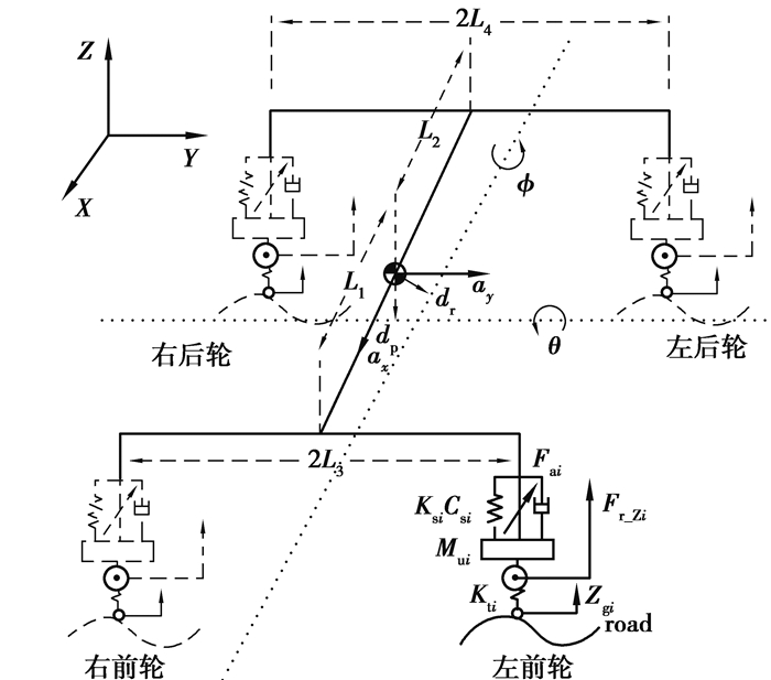
笔者建立考虑电机电磁力和主动悬架作动力的电动汽车7自由度动力学模型,如图 3所示。电机不平衡垂向力合力作为系统外力作用于车轮,整个系统符合右手坐标系。
|
图 3 7自由度整车模型 Figure 3 Vehicle model in 7 degrees of freedom |
簧载质量垂直振动方程为
| $ {m_{\rm{s}}}\ddot z = \sum {{F_{{\rm{s}}i}}} , $ | (14) |
式中:ms为簧载质量;
| $ {F_{{\rm{s}}i}} = {K_{{\rm{s}}i}}\left( {{z_{{\rm{u}}i}} - {z_{{\rm{s}}i}}} \right) + {C_{{\rm{s}}i}}\left( {{{\dot z}_{{\rm{u}}i}} - {{\dot z}_{{\rm{s}}i}}} \right) + {F_{{\rm{a}}i}}, $ | (15) |
式中:zsi为悬架与车身连接点处的位移;zui为簧下质量的位移;Ksi、Csi分别为悬架的刚度和阻尼;Fai为主动悬架所提供的主动作动力。i=1, 2, 3, 4分别代表车辆的左前、左后、右前及右后悬架。z与zsi的换算关系为
| $ \begin{array}{*{20}{c}} {{z_{{\rm{s1}}}} = z - {L_1}\theta + {L_3}\phi ,}\\ {{z_{{\rm{s2}}}} = z + {L_2}\theta + {L_4}\phi ,}\\ {{z_{{\rm{s3}}}} = z - {L_1}\theta - {L_3}\phi ,}\\ {{z_{{\rm{s4}}}} = z + {L_2}\theta - {L_4}\phi ,} \end{array} $ | (16) |
式中:ϕ和θ分别是车身的侧倾角和俯仰角;L1、L2、L3和L4分别代表车辆质心到前/后轴的距离以及前/后的半轮距。
非簧载质量的振动方程为
| $ {m_{{\rm{u}}i}}{{\ddot z}_{{\rm{u}}i}} = {F_{{\rm{tz}}i}} - {F_{{\rm{s}}i}}, $ | (17) |
式中mui、zui分别表示非簧载质量及其位移,轮胎垂向力Ftzi为
| $ {F_{{\rm{tz}}i}} = {K_{{\rm{t}}i}}\left( {{z_{{\rm{g}}i}} - {z_{{\rm{u}}i}}} \right) + {F_{{\rm{r\_Z}}i}}, $ | (18) |
式中:Fr_Zi为电机不平衡径向力在车辆垂向的分量;Kti为轮胎刚度;zgi为路面位移。
忽略惯性积影响,根据达朗贝尔原理,在惯性加速度下簧载质量的侧倾运动和俯仰运动分别为
侧倾运动
| $ {I_x}\ddot \phi = \left( {{F_{{\rm{s1}}}} - {F_{{\rm{s3}}}}} \right){L_3} + \left( {{F_{{\rm{s2}}}} - {F_{{\rm{s4}}}}} \right){L_4} + {m_{\rm{s}}}{a_y}{d_{\rm{r}}} + {m_{\rm{s}}}g{d_{\rm{r}}}\phi , $ | (19) |
俯仰运动
| $ {I_y}\ddot \theta = \left( {{F_{{\rm{s2}}}} + {F_{{\rm{s4}}}}} \right){L_2} - \left( {{F_{{\rm{s1}}}} + {F_{{\rm{s3}}}}} \right){L_1} + {m_{\rm{s}}}{a_x}{d_{\rm{p}}} + {m_{\rm{s}}}g{d_{\rm{p}}}\theta , $ | (20) |
式中:g为重力加速度;Ix和Iy分别表示车身的侧倾和俯仰转动惯量;ax、ay分别表示由车辆加速/制动/转向运动而施加在车辆质心处的纵、侧向惯性加速度;dr和dp分别表示车辆质心到侧倾、俯仰轴的距离。
定义:
| $ {\mathit{\boldsymbol{F}}_{\rm{a}}} = {\left[ {{F_{{\rm{a1}}}},{F_{{\rm{a2}}}},{F_{{\rm{a3}}}},{F_{{\rm{a4}}}}} \right]^{\rm{T}}}, $ |
| $ {\mathit{\boldsymbol{F}}_{{\rm{r\_Z}}}} = {\left[ {{F_{{\rm{r\_Z1}}}},{F_{{\rm{r\_Z2}}}},{F_{{\rm{r\_Z3}}}},{F_{{\rm{r\_Z4}}}}} \right]^{\rm{T}}}, $ |
| $ {\mathit{\boldsymbol{C}}_{\rm{s}}} = {\rm{diag}}\left( {{C_{{\rm{s1}}}},{C_{{\rm{s2}}}},{C_{{\rm{s3}}}},{C_{{\rm{s4}}}}} \right), $ |
| $ {\mathit{\boldsymbol{Z}}_{\rm{s}}} = {\left[ {z,\phi ,\theta } \right]^{\rm{T}}}, $ |
| $ {\mathit{\boldsymbol{Z}}_{\rm{u}}} = {\left[ {{z_{{\rm{u1}}}},{z_{{\rm{u2}}}},{z_{{\rm{u3}}}},{z_{{\rm{u4}}}}} \right]^{\rm{T}}}, $ |
| $ {\mathit{\boldsymbol{Z}}_g} = {\left[ {{z_{{\rm{g1}}}},{z_{{\rm{g2}}}},{z_{{\rm{g3}}}},{z_{{\rm{g4}}}}} \right]^{\rm{T}}}, $ |
| $ {\mathit{\boldsymbol{Z}}_{\rm{a}}} = {\left[ {{a_y},{a_x}} \right]^{\rm{T}}}, $ |
| $ {\mathit{\boldsymbol{M}}_{\rm{s}}} = {\rm{diag}}\left( {{m_{\rm{s}}},{I_x},{I_y}} \right), $ |
| $ {\mathit{\boldsymbol{M}}_{\rm{u}}} = {\rm{diag}}\left( {{m_{{\rm{u1}}}},{m_{{\rm{u2}}}},{m_{{\rm{u3}}}},{m_{{\rm{u4}}}}} \right), $ |
| $ {\mathit{\boldsymbol{K}}_{\rm{t}}} = {\rm{diag}}\left( {{K_{{\rm{t1}}}},{K_{{\rm{t2}}}},{K_{{\rm{t3}}}},{K_{{\rm{t4}}}}} \right), $ |
| $ {\mathit{\boldsymbol{K}}_{\rm{s}}} = {\rm{diag}}\left( {{K_{{\rm{s1}}}},{K_{{\rm{s2}}}},{K_{{\rm{s3}}}},{K_{{\rm{s4}}}}} \right), $ |
| $ \mathit{\boldsymbol{L}} = \left[ {\begin{array}{*{20}{c}} 1&{{L_3}}&{ - {L_1}}\\ 1&{{L_4}}&{{L_2}}\\ 1&{ - {L_3}}&{ - {L_1}}\\ 1&{ - {L_4}}&{{L_2}} \end{array}} \right]{\mathit{\boldsymbol{L}}_{{\rm{m1}}}} = {m_{\rm{s}}}\left[ {\begin{array}{*{20}{c}} 0&0\\ {{d_{\rm{r}}}}&0\\ 0&{{d_{\rm{p}}}} \end{array}} \right], $ |
| $ {\mathit{\boldsymbol{L}}_{{\rm{m2}}}} = {m_{\rm{s}}}g\left[ {\begin{array}{*{20}{c}} 0&0&0\\ 0&{{d_{\rm{r}}}}&0\\ 0&0&{{d_{\rm{p}}}} \end{array}} \right]。$ |
将上述方程表述为状态空间的标准形式:
| $ \begin{array}{*{20}{c}} {\mathit{\boldsymbol{\dot X}} = \mathit{\boldsymbol{AX}} + \mathit{\boldsymbol{BU}} + \mathit{\boldsymbol{GW}},}\\ {\mathit{\boldsymbol{Y}} = \mathit{\boldsymbol{CX}} + \mathit{\boldsymbol{DU}} + \mathit{\boldsymbol{HW}}。} \end{array} $ | (21) |
其中状态变量为
| $ \mathit{\boldsymbol{X}} = \left[ {{\mathit{\boldsymbol{Z}}_{\bf{s}}},{{\mathit{\boldsymbol{\dot Z}}}_{\bf{s}}},{\mathit{\boldsymbol{Z}}_{\bf{u}}} - \mathit{\boldsymbol{L}}{\mathit{\boldsymbol{Z}}_{\bf{s}}},{\mathit{\boldsymbol{Z}}_\mathit{\boldsymbol{g}}} - {\mathit{\boldsymbol{Z}}_{\bf{u}}},{{\mathit{\boldsymbol{\dot Z}}}_{\bf{u}}}} \right]_{1 \times 18}^{\rm{T}}。$ |
输出变量为
| $ \mathit{\boldsymbol{Y }} = \left[ {{{\mathit{\boldsymbol{\ddot Z}}}_{\bf{s}}},{\mathit{\boldsymbol{Z}}_{\bf{s}}},{\mathit{\boldsymbol{Z}}_{\bf{u}}} - \mathit{\boldsymbol{L}}{\mathit{\boldsymbol{Z}}_{\bf{s}}},{\mathit{\boldsymbol{Z}}_\mathit{\boldsymbol{g}}} - {\mathit{\boldsymbol{Z}}_{\bf{u}}}} \right]_{1 \times 14}^{\rm{T}}。$ |
输入变量为主动悬架的作动力
| $ \mathit{\boldsymbol{U}} = {\left[ {{\mathit{\boldsymbol{F}}_{\rm{a}}}} \right]_{4 \times 1}}。$ |
相关的矩阵为
| $ \mathit{\boldsymbol{A}} = {\left[ {\begin{array}{*{20}{c}} {{{\bf{0}}_{3 \times 3}}}&{{{\bf{1}}_{3 \times 3}}}&{{{\bf{0}}_{3 \times 4}}}&{{{\bf{0}}_{3 \times 4}}}&{{{\bf{0}}_{3 \times 4}}}\\ {{\mathit{\boldsymbol{M}}^{\rm{m}}} - {1_{\rm{s}}}{\mathit{\boldsymbol{L}}_{{\rm{m2}}}}}&{ - \mathit{\boldsymbol{M}}_{\rm{s}}^{ - 1}{\mathit{\boldsymbol{L}}^{\rm{T}}}{\mathit{\boldsymbol{C}}_{\rm{s}}}\mathit{\boldsymbol{L}}}&{{\mathit{\boldsymbol{M}}^{\rm{m}}} - {1_{\rm{s}}}{\mathit{\boldsymbol{L}}^{\rm{T}}}{\mathit{\boldsymbol{K}}_{\rm{s}}}}&{{{\bf{0}}_{3 \times 4}}}&{\mathit{\boldsymbol{M}}_{\rm{s}}^{ - 1}{\mathit{\boldsymbol{L}}^{\rm{T}}}{\mathit{\boldsymbol{L}}_{\rm{s}}}}\\ {{{\bf{0}}_{4 \times 3}}}&{ - \mathit{\boldsymbol{L}}}&{{{\bf{0}}_{4 \times 4}}}&{{{\bf{0}}_{4 \times 4}}}&{{{\bf{1}}_{4 \times 4}}}\\ {{{\bf{0}}_{4 \times 3}}}&{{{\bf{0}}_{4 \times 3}}}&{{{\bf{0}}_{4 \times 4}}}&{{{\bf{0}}_{4 \times 4}}}&{ - {{\bf{1}}_{4 \times 4}}}\\ {{{\bf{0}}_{4 \times 3}}}&{\mathit{\boldsymbol{M}}_{\rm{u}}^{ - 1}{\mathit{\boldsymbol{C}}_{\rm{s}}}\mathit{\boldsymbol{L}}}&{ - \mathit{\boldsymbol{M}}_{\rm{u}}^{ - 1}{\mathit{\boldsymbol{K}}_{\rm{s}}}}&{\mathit{\boldsymbol{M}}_{\rm{u}}^{ - 1}{\mathit{\boldsymbol{K}}_t}}&{ - \mathit{\boldsymbol{M}}_{\rm{u}}^{ - 1}{\mathit{\boldsymbol{C}}_{\rm{s}}}} \end{array}} \right]_{18 \times 18}}, $ |
| $ \mathit{\boldsymbol{B}} = {\left[ \begin{array}{l} {{\bf{0}}_{3 \times 4}}\\ \mathit{\boldsymbol{M}}_{\rm{s}}^{ - 1}{\mathit{\boldsymbol{L}}^{\rm{T}}}\\ {{\bf{0}}_{4 \times 4}}\\ {{\bf{0}}_{4 \times 4}}\\ - \mathit{\boldsymbol{M}}_{\rm{u}}^{ - 1} \end{array} \right]_{18 \times 4}}, $ |
| $ \mathit{\boldsymbol{C}} = {\left[ {\begin{array}{*{20}{c}} {\mathit{\boldsymbol{M}}_{\rm{s}}^{ - 1}{\mathit{\boldsymbol{L}}_{{\rm{m2}}}}}&{ - \mathit{\boldsymbol{M}}_{\rm{s}}^{ - 1}{\mathit{\boldsymbol{L}}^{\rm{T}}}{\mathit{\boldsymbol{C}}_{\rm{s}}}L}&{{\mathit{\boldsymbol{M}}^m} - {1_{\rm{s}}}{\mathit{\boldsymbol{L}}^{\rm{T}}}{\mathit{\boldsymbol{K}}_{\rm{s}}}}&{{{\bf{0}}_{3 \times 3}}}&{\mathit{\boldsymbol{M}}_{\rm{s}}^{ - 1}{\mathit{\boldsymbol{L}}^{\rm{T}}}{\mathit{\boldsymbol{C}}_{\rm{s}}}}\\ {{{\bf{1}}_{3 \times 3}}}&{{{\bf{0}}_{3 \times 3}}}&{{{\bf{0}}_{3 \times 4}}}&{{{\bf{0}}_{3 \times 4}}}&{{{\bf{0}}_{3 \times 4}}}\\ {{{\bf{0}}_{4 \times 3}}}&{{{\bf{0}}_{4 \times 3}}}&{{{\bf{1}}_{4 \times 4}}}&{{{\bf{0}}_{4 \times 4}}}&{{{\bf{0}}_{4 \times 4}}}\\ {{{\bf{0}}_{4 \times 3}}}&{{{\bf{0}}_{4 \times 3}}}&{{{\bf{0}}_{4 \times 4}}}&{{{\bf{1}}_{4 \times 4}}}&{{{\bf{0}}_{4 \times 4}}} \end{array}} \right]_{14 \times 18}}, $ |
| $ \mathit{\boldsymbol{D}} = {\left[ \begin{array}{l} \mathit{\boldsymbol{M}}_{\rm{s}}^{ - 1}{\mathit{\boldsymbol{L}}^{\rm{T}}}\\ {{\bf{0}}_{3 \times 4}}\\ {{\bf{0}}_{4 \times 4}}\\ {{\bf{0}}_{4 \times 4}} \end{array} \right]_{14 \times 14}},\mathit{\boldsymbol{G}} = {\left[ {\begin{array}{*{20}{c}} {{{\bf{0}}_{3 \times 2}}}&{{{\bf{0}}_{3 \times 4}}}&{{{\bf{0}}_{3 \times 4}}}\\ {\mathit{\boldsymbol{M}}_{\rm{s}}^{ - 1} - {\mathit{\boldsymbol{L}}_{{\rm{m1}}}}}&{{{\bf{0}}_{3 \times 4}}}&{{{\bf{0}}_{3 \times 4}}}\\ {{{\bf{0}}_{4 \times 2}}}&{{{\bf{0}}_{4 \times 4}}}&{{{\bf{0}}_{3 \times 4}}}\\ {{{\bf{0}}_{4 \times 2}}}&{{{\bf{1}}_{4 \times 4}}}&{{{\bf{0}}_{4 \times 4}}}\\ {{{\bf{0}}_{4 \times 2}}}&{{{\bf{0}}_{4 \times 4}}}&{ - \mathit{\boldsymbol{M}}_{\rm{u}}^{ - 1}} \end{array}} \right]_{18 \times 10}}, $ |
| $ \mathit{\boldsymbol{H}} = {\left[ {\begin{array}{*{20}{c}} {\mathit{\boldsymbol{M}}_{\rm{s}}^{ - 1}{\mathit{\boldsymbol{L}}_{{\rm{m1}}}}}&{{{\bf{0}}_{3 \times 4}}}&{{{\bf{0}}_{3 \times 4}}}\\ {{{\bf{0}}_{3 \times 2}}}&{{{\bf{0}}_{3 \times 4}}}&{{{\bf{0}}_{3 \times 4}}}\\ {{{\bf{0}}_{4 \times 2}}}&{{{\bf{0}}_{4 \times 4}}}&{{{\bf{0}}_{4 \times 4}}}\\ {{{\bf{0}}_{4 \times 2}}}&{{{\bf{0}}_{4 \times 4}}}&{{{\bf{0}}_{4 \times 4}}} \end{array}} \right]_{14 \times 10}}, $ |
| $ \mathit{\boldsymbol{W}} = \left[ {{\mathit{\boldsymbol{Z}}_{\rm{a}}},{\mathit{\boldsymbol{Z}}_{\rm{g}}},{\mathit{\boldsymbol{F}}_{{\rm{r\_Z}}}}} \right]_{10 \times 1}^{\rm{T}}。$ |
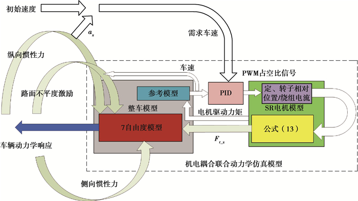
机电耦合系统联合仿真动力学模型逻辑框图如图 4。电机调速PID控制器根据当前车速和需求车速之差计算出PWM占空比来控制电机的绕组电压。电机模型根据绕组电流,定、转子相对位移计算出电机的驱动力矩和不平衡电磁力。分别输入到参考模型和7自由度模型中。参考模型用于计算实际车速,使用1/4单轮模型,车轮旋转方程为
| $ {I_{\rm{t}}}\ddot \omega = {T_{\rm{e}}} - {F_{{\rm{t}}x}}{R_{\rm{e}}} - {m_{\rm{t}}}, $ | (22) |
|
图 4 联合模型逻辑框图 Figure 4 Logical diagram of the joint model |
式中:It为车轮及车身质量等效的转动惯量;
多目标优化设计的目的是减小电机不平衡径向力对四轮独立驱动轮毂电机电动汽车的系统动力学性能影响。为了对其进行量化,将方程(21)变换为以扰动W为输入的模型:
| $ \begin{array}{*{20}{c}} {\mathit{\boldsymbol{\dot X}} = \left( {\mathit{\boldsymbol{A}} - \mathit{\boldsymbol{BK}}} \right)\mathit{\boldsymbol{X}} + \mathit{\boldsymbol{GW}},}\\ {\mathit{\boldsymbol{Y}} = \left( {\mathit{\boldsymbol{C}} - \mathit{\boldsymbol{DK}}} \right)\mathit{\boldsymbol{X}} + \mathit{\boldsymbol{HW}}。} \end{array} $ | (23) |
根据式(23)求出Y中车辆动力学响应对W中Fr_Z的传递特性并分类,将电机不平衡径向力对簧载质量振动加速度/俯仰角/悬架动扰度的振动传递特性归类为平顺性指标;侧倾角/轮胎动载荷的振动传递特性作为操稳性指标。
设计电动汽车的行驶速度范围为0~100 km/h,对应的轮毂电机垂向力激励频率为0~140 Hz,分别将这一范围内振动传递特性曲线包围的面积和幅值作为量化的目标函数,利用被动悬架响应进行归一化处理。
1) 平顺性指标。
| $ {F_1}\left( x \right) = \ddot z \to {\mathit{\boldsymbol{F}}_{{\rm{r\_Z}}}}, $ |
| $ {F_2}\left( x \right) = \theta \to {\mathit{\boldsymbol{F}}_{{\rm{r\_Z}}}}, $ |
| $ \begin{array}{*{20}{c}} {{F_3}\left( x \right) = \left[ {{{\left( {{\mathit{\boldsymbol{Z}}_{\rm{u}}} - \mathit{\boldsymbol{L}}{\mathit{\boldsymbol{Z}}_{\rm{s}}}} \right)}_1}} \right] \to {F_{{\rm{r\_}}{{\rm{z}}_1}}} + \left[ {{{\left. {{{\left( \mathit{\boldsymbol{Z}} \right)}_{\rm{u}}} - \mathit{\boldsymbol{L}}{\mathit{\boldsymbol{Z}}_{\rm{S}}}} \right)}_2} \to {F_{{\rm{r\_}}{{\rm{z}}_2}}}} \right] + }\\ {\left[ {{{\left. {{{\left( Z \right)}_{\rm{u}}} - \mathit{\boldsymbol{L}}{\mathit{\boldsymbol{Z}}_{\rm{S}}}} \right)}_3} \to {F_{{\rm{r}}{{\rm{z}}_3}}}} \right] + \left[ {{{\left( {{\mathit{\boldsymbol{Z}}_{\rm{u}}} - \mathit{\boldsymbol{L}}{\mathit{\boldsymbol{Z}}_{\rm{s}}}} \right)}_4} \to {F_{{\rm{r}}{{\rm{z}}_4}}}} \right]。} \end{array} $ |
2) 操稳性指标。
| $ {F_4}\left( x \right) = \varphi \to {\mathit{\boldsymbol{F}}_{r\_Z}}, $ |
| $ \begin{array}{*{20}{c}} {{F_5}\left( x \right) = \left[ {{K_{{\rm{t1}}}}{{\left( {{\mathit{\boldsymbol{Z}}_{\rm{g}}} - {\mathit{\boldsymbol{Z}}_{\rm{u}}}} \right)}_1} \to {F_{{\rm{r\_}}{{\rm{z}}_1}}}} \right] + \left[ {{K_{{\rm{t2}}}}{{\left( {{\mathit{\boldsymbol{Z}}_{\rm{g}}} - {\mathit{\boldsymbol{Z}}_{\rm{u}}}} \right)}_2} \to {F_{{\rm{r\_}}{{\rm{z}}_2}}}} \right] + }\\ {\left[ {{K_{{\rm{t3}}}}{{\left( {{\mathit{\boldsymbol{Z}}_{\rm{g}}} - {\mathit{\boldsymbol{Z}}_{\rm{u}}}} \right)}_3} \to {F_{{\rm{r\_}}{{\rm{z}}_3}}}} \right] + \left[ {{K_{{\rm{t4}}}}{{\left( {{\mathit{\boldsymbol{Z}}_{\rm{g}}} - {\mathit{\boldsymbol{Z}}_{\rm{u}}}} \right)}_4} \to {F_{{\rm{r\_}}{{\rm{z}}_4}}}} \right]。} \end{array} $ |
选择悬架系统的刚度(Ks)和阻尼(Cs),以及悬架LQR控制器的2个加权矩阵Q和R作为优化变量。优化变量的基准值为原始被动悬架的参数, 优化的取值范围根据实际情况来选择,弹簧刚度根据普通轿车的偏频范围来选择,满载的偏频一般为1.00~1.45 Hz,主悬架刚度取值范围为0.75~2.50倍原被动悬架基准值,阻尼器的阻尼大小和尺寸有很大的关系,不能在较大范围内变化,选取0.25~1.50倍原被动悬架基准值。此外,需限制车辆时域的动态性能:仿真工况下车辆各自由度动力学响应均方根值不大于使用被动悬架车辆的1.40倍为时域性能约束。具体表达式如下。
优化变量:
| $ x = \left[ {{K_{{\rm{s}}i}},{C_{{\rm{s}}i}},{a_1}, \cdots ,{a_{14}},{b_1}, \cdots ,{b_4}} \right]。$ |
约束条件:
| $ {K_{{\rm{s}}i}} \in \left[ {0.75,2.5} \right] \cdot {K_{si\left( {{\rm{passive}}} \right)}}, $ |
| $ {C_{{\rm{s}}i}} \in \left[ {0.25,1.5} \right] \cdot {C_{si\left( {{\rm{passive}}} \right)}}, $ |
| $ {a_1}, \cdots ,{a_{14}} \in \left[ {1,1{{\rm{e}}^{10}}} \right], $ |
| $ {b_1}, \cdots ,{b_4} \in \left[ {1,1{{\rm{e}}^{10}}} \right], $ |
| $ {\rm{rms}}\left( {\ddot z} \right) \le 1.4 \times {\rm{rms}}{\left( {\ddot z} \right)_{{\rm{passive}}}}, $ |
| $ {\rm{rms}}\left( \theta \right) \le 1.4 \times {\rm{rms}}{\left( \theta \right)_{{\rm{passive}}}}, $ |
| $ {\rm{rms}}\left( {{\mathit{\boldsymbol{Z}}_{\rm{u}}} - \mathit{\boldsymbol{L}}{\mathit{\boldsymbol{Z}}_{\rm{s}}}} \right) \le 1.4 \times {\rm{rms}}{\left( {{\mathit{\boldsymbol{Z}}_{\rm{u}}} - \mathit{\boldsymbol{L}}{\mathit{\boldsymbol{Z}}_{\rm{s}}}} \right)_{{\rm{passive}}}}, $ |
| $ {\rm{rms}}\left( \varphi \right) \le 1.4 \times {\rm{rms}}{\left( \varphi \right)_{{\rm{passive}}}}, $ |
| $ {\rm{rms}}{\mathit{\boldsymbol{K}}_t}\left( {{\mathit{\boldsymbol{Z}}_{\rm{g}}} - {\mathit{\boldsymbol{Z}}_{\rm{u}}}} \right) \le 1.4 \times {\rm{rms}}{\mathit{\boldsymbol{K}}_t}{\left( {{\mathit{\boldsymbol{Z}}_{\rm{g}}} - {\mathit{\boldsymbol{Z}}_{\rm{u}}}} \right)_{{\rm{passive}}}}。$ |
根据动力学模型的对称性,
| $ {a_7} = {a_8} = {a_9} = {a_{10}}, $ |
| $ {a_{11}} = {a_{12}} = {a_{13}} = {a_{14}}, $ |
| $ {b_1} = {b_2} = {b_3} = {b_4}。$ |
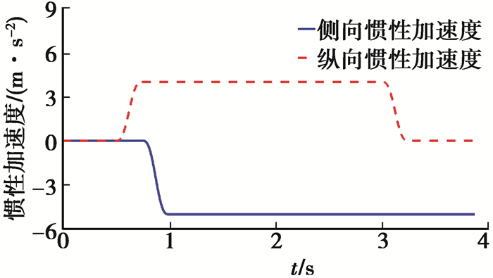
笔者采用了一种联合转向、制动和随机路面激励的联合仿真工况[17]。C级随机路面作为路面输入,横向/纵向惯性加速度如图 5所示,初始速度为15 km/h。
|
图 5 联合仿真工况 Figure 5 Combined test case |
采用粒子群优化算法(MOPSO)求解上述多目标优化问题。选取参数如下:种群数量400,初始值W=0.7,终止值W=0.4,加权因子R1和R2取0和1之间的随机数,约束因子a=0.5,迭代步长800。
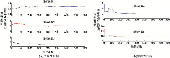
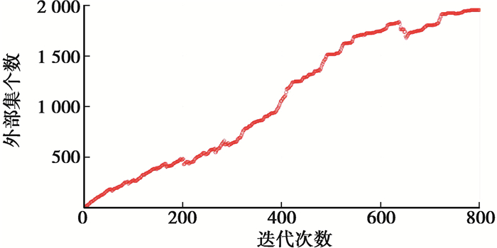
目标函数迭代过程如图 6所示,纵坐标为目标函数平均值。外部集个数如图 7所示。可以看出,多目标算法变量的群体分布在500代后趋于稳定。优化结果列于表 1,选取“*”解集用于对比和分析。
|
图 6 目标函数平均适应度值 Figure 6 Mean value of fitness function |
|
图 7 外部集个数 Figure 7 Number of external solution set |
| 表 1 优化前后悬架参数 Table 1 Original and optimized suspension parameters |
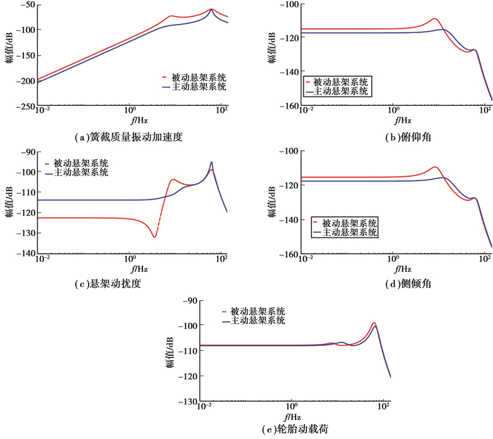
图 8为垂向不平衡径向力振动传递特性对比,选取左前轮进行分析。
|
图 8 振动传递特性 Figure 8 Vibration transfer characteristics |
图 8(a)表明,簧载质量加速度响应在一阶共振频率附近略有衰减,削弱了在1 Hz左右的车身共振频率范围电机垂向激励对簧载质量的影响。图 8(b)(d)表明,主动悬架改善了车身姿态对不平衡径向力的低频响应,使其更趋近于稳定,提高了车辆启动和制动工况下的乘坐舒适性。但是,引入主动悬架控制后电机垂向激励对车辆非簧载质量的影响改善效果并不明显(图 8(e)), 甚至恶化(图 8(c))。这是由于优化解集控制目标更偏重于簧载质量的动力学响应,控制器将多余作动器能量传递到簧下。但是总体上来说,可以削弱不平衡径向力对车辆乘坐舒适性的影响。
4.2 时域响应仿真工况下的时域响应均方根值对比如表 2所示。可以看出,主动悬架系统同时改善了车辆系统的时域动力学响应。另外注意到车轮动载荷响应恶化,车辆动力学系统的优化问题为平顺性和操稳性的折中,无专门设计的目标函数导致了主动悬架能量溢出,结论与4.1一致。
| 表 2 仿真工况下动力学响应均方根值 Table 2 Dynamic responses under test case |
笔者在分析轮毂电机驱动系统电磁力激振特性的基础上,通过对电磁主动悬架系统的多目标优化设计,解决其振动负效应问题。研究结果表明:
1) 四轮独立驱动电动汽车所采用的轮毂电机驱动系统由机电耦合效应带来的电磁激振力,造成车辆动力学性能恶化。在轮毂驱动电动车平顺性研究中,振动负效应应予以重点考虑。
2) 多目标设计后的主动悬架能有效抑制不平衡电磁激振力在车辆簧上引起的振动负效应,改善车辆系统的垂向动力学响应。
| [1] |
Wang Y Y, Li P F, Ren G Z. Electric vehicles with in-wheel switched reluctance motors:Coupling effects between road excitation and the unbalanced radial force[J]. Journal of Sound and Vibration, 2016, 372: 69-81. DOI:10.1016/j.jsv.2016.02.040 |
| [2] |
Wang Y Y, Li Y N, Sun W, et al. Effect of the unbalanced vertical force of a switched reluctance motor on the stability and the comfort of an in-wheel motor electric vehicle[J]. Proceedings of the Institution of Mechanical Engineers, Part D:Journal of Automobile Engineering, 2015, 229(12): 1569-1584. DOI:10.1177/0954407014566438 |
| [3] |
Tan D, Lu C. The influence of the magnetic force generated by the in-wheel motor on the vertical and lateral coupling dynamics of electric vehicles[J]. IEEE Transactions on Vehicular Technology, 2016, 65(6): 4655-4668. DOI:10.1109/TVT.2015.2461635 |
| [4] |
Sun W, Li Y N, Huang J Y, et al. Vibration effect and control of In-Wheel Switched Reluctance Motor for electric vehicle[J]. Journal of Sound and Vibration, 2015, 338: 105-120. DOI:10.1016/j.jsv.2014.10.036 |
| [5] |
Luo Y T, Tan D. Study on the dynamics of the in-wheel motor system[J]. IEEE Transactions on Vehicular Technology, 2012, 61(8): 3510-3518. DOI:10.1109/TVT.2012.2207414 |
| [6] |
Tan D, Lu C, Ren C B. Optimal matching between the suspension and the rubber bushing of the in-wheel motor system[J]. Proceedings of the Institution of Mechanical Engineers, Part D:Journal of Automobile Engineering, 2015, 229(6): 758-769. DOI:10.1177/0954407014547928 |
| [7] |
王艳阳, 李以农, 裴金顺, 等. 车用电磁悬架能量转换特性的功率流分析方法[J]. 重庆大学学报, 2013, 36(5): 1-7. WANG Yanyang, LI Yinng, PEI Jinshun, et al. Energy conversion analysis of vehicle electromagnetic suspension using power flow method[J]. Journal of Chongqing University, 2013, 36(5): 1-7. (in Chinese) |
| [8] |
Xue X D, Cheng K W E, Ng T W, et al. Multi-objective optimization design of in-wheel switched reluctance motors in electric vehicles[J]. IEEE Transactions on Industrial Electronics, 2010, 57(9): 2980-2987. DOI:10.1109/TIE.2010.2051390 |
| [9] |
Lin J, Cheng K W E, Zhang Z, et al. Experimental investigation of in-wheel switched reluctance motor driving system for future electric vehicles[C]//20093rd International Conference on Power Electronics Systems and Applications, May 20-22, 2009, Hong Kong, China. IEEE, 2009: 1-6.
|
| [10] |
Xue X D, Cheng K W E, Lin J K, et al. Optimal control method of motoring operation for SRM drives in electric vehicles[J]. IEEE Transactions on Vehicular Technology, 2010, 59(3): 1191-1204. DOI:10.1109/TVT.2010.2041260 |
| [11] |
Wong K F, Cheng K W E, Ho S L. Simulation of switched reluctance motor based on a combination of circuit-oriented and signal-oriented approaches using Matlab/SimPowerSystems[J]. Electric Power Components and Systems, 2007, 35(2): 205-219. DOI:10.1080/15325000600891218 |
| [12] |
Fahimi B, Suresh G, Mahdavi J, et al. A new approach to model switched reluctance motor drive application to dynamic performance prediction, control and design[C]//PESC 98 Record. 29th Annual IEEE Power Electronics Specialists Conference (Cat. no.98CH36196), May 22-22, 1998, Fukuoka, Japan. IEEE, 1998: 2097-2102.
|
| [13] |
Husain I, Ehsani M. Torque ripple minimization in switched reluctance motor drives by PWM current control[J]. IEEE Transactions on Power Electronics, 1996, 11(1): 83-88. DOI:10.1109/63.484420 |
| [14] |
Mahdavi J, Suresh G, Fahimi B, et al. Dynamic modeling of nonlinear SRM drive with Pspice[C]//IAS'97. Conference Record of the 1997 IEEE Industry Applications Conference Thirty-Second IAS Annual Meeting, October 5-9, 1997, New Orleans, LA, USA. IEEE, 1997: 661-667.
|
| [15] |
Krishnamurthy M, Edrington C S, Emadi A, et al. Making the case for applications of switched reluctance motor technology in automotive products[J]. IEEE Transactions on Power Electronics, 2006, 21(3): 659-675. DOI:10.1109/TPEL.2006.872371 |
| [16] |
Cameron D E, Lang J H, Umans S D. The origin of acoustic noise in variable-reluctance motors[C]//Conference Record of the IEEE Industry Applications Society Annual Meeting, October 1-5, 1989, San Diego, CA, USA. IEEE, 1989: 108-115.
|
| [17] |
Lu S B, Li Y N, Choi S B. Contribution of chassis key subsystems to rollover stability control[J]. Proceedings of the Institution of Mechanical Engineers, Part D:Journal of Automobile Engineering, 2012, 226(4): 479-493. DOI:10.1177/0954407011421850 |
 2019, Vol. 42


